Making your first product
About this tutorial
This tutorial is intended as a learning for the configuration of products in 3D product configurator. This tutorial does not require any prior experience, but will not comprehensively describe all parameters needed to be used here.
Note
Tutorial is bit out of sync from the actual screens of the Management UI and some parameters are not correct (related to accessory leg positioning). This does not affect functionality and you should be able to discover the correct values of parameters on your own.
Assumptions You have only single tenant access and if you have access to many tenants, this tutorial assumes you select a tenant where the tutorial sofa product is configured. This tutorial flows from one step to another and will take few hours from your time, mostly due to the fact that you are not familiar with any of the concepts and ways of doing in the configurator. Additionally, this tutorial might be bit out of date compared to some visuals and screens of the management UI.
Your first login to the Manager
When you login to the system you either automatically are moved to your tenant or you are given tenant selection screen from where you can choose which tenant you manage, depending on how many tenants you have access to. Select a tenant if necessary.
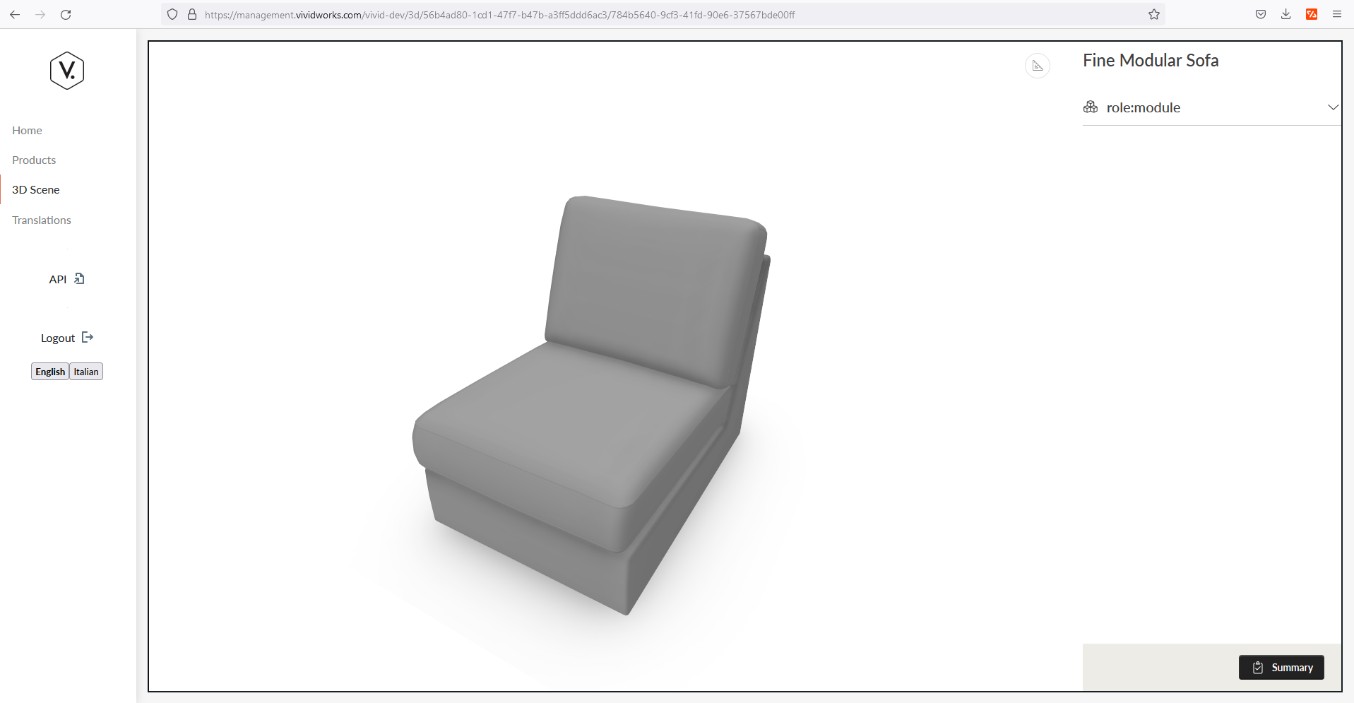
Next, The main manager screen will open for you, it looks empty in the beginning but after completing this tutorial, you have created your first modular sofa product using the 3D product configurator.
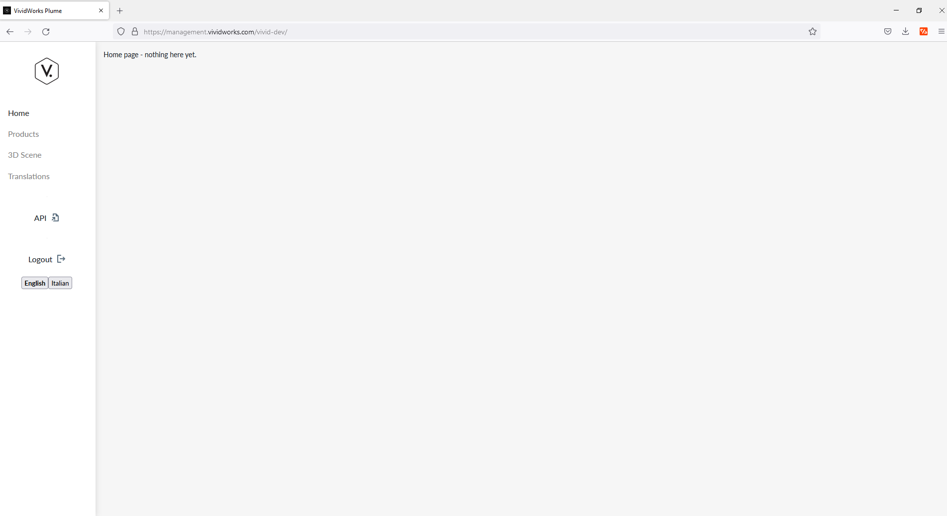
Quick view of the manager main screen and various elements
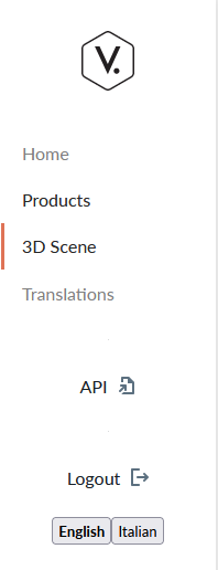
Left Menubar
The left Menu area contains links to the main functions of the Manager
- Home
- Products
- 3D Scene
- Translations
- API
- Logout
- Translations of the Manager
Products
From the Left menu bar, click on "Products" link to open the environment where product configuration happens, majority of activity in the tutorial will be performed here.

Lets quickly go through the main elements of the products view
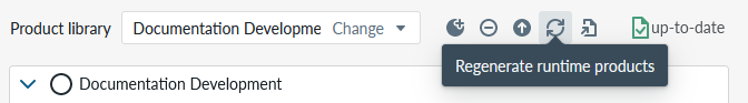
Top Menubar

The top menubar contains a selection box for the product library you are working on, activity buttons for Upload New Assets, Regenerating runtime products, and one or two links to view the products of the product library in the planner view plus a status indicator for the save state of the configuration.
Product libraries themselves are managed from the Product Libraries list page. From there you can create a new library with the New Library button, and access per-library actions — Tags, History, Rename, and Delete — through the action menu (⋯) on each library row.
Product Library
The idea behind product library is to be a container for a set of products that share common elements with each other, be them elements, materials, accessories or alike.
You can create, rename, and delete product libraries from the Product Libraries list page.
Upload New Assets
Through this button you are able to upload new assets (Images, Textures, 3D models, and cubemaps) In this tutorial we are not uploading new assets, but you will need this function to managing your assets. Alternatively you can use drag-and-drop upload feature which is explained elsewhere
Regenerate Runtime Products
The way the 3D ecommerce configurator works is that 3d models and their configurations that are shown in the planner side are not continuosly applied (generated) to save compute and I/O capacity. When you want to test or apply the changes and view them, you need to regenerate them and only after that you will see the changes take effect.
The Manager now automatically runs a targeted regenerate for the selected product every time you open any 3D view or launch the Pre Built Component editor. The Regenerate button is still available for batch scenarios (for example, refreshing many products before a demo) and for surfacing warnings before you open the 3D view, but you can rely on the automatic regenerate to keep previews and pre-built edits consistent.
Links to view products in the planner
In the top menubar, depending on what is selected in the Product Tree Panel, you either have 1 or 2 link icons. IF you have selected a product in the Product Tree Panel, the 2nd link appears which opens the planner view for this particular product, based on the latest generated runtime products. If the view does not load any data to you, the most likely reason is that no runtime products have been generated and you can resolve the issue by clicking the Regenerate Runtime Products icon.
NOTE for the reader: In this tutorial we are going to ask you to "Regenerate the runtime products and open the planner" which means that you press the Regenerate Runtime Products button, wait for the spinner to indicate that the changes are updated and then select the product in the product view and select the link "View First Sofa Product" on the top menubar of Products View. Today the platform launches that regenerate automatically just before the planner or pre-built editor opens, so if you forget the manual step the system will still pause for the regenerate before the 3D view appears.
Product tree panel
Product Tree Panel in the center contains the products in the product library and the tree structure of how the rules, 3D models, Materials, and everything else will be assebled. The Tree contains quite many options for construction and this tutorial will start from pretty basic configuration and move to more advanced ways as we build.
Component configuration panel
Component configuration panel on the right is the place where the parameters of the item selected in the Product Tree Panel is selected are managed.
3D Scene
The 3D Scene link opens the planner for the product library you have selected
Translations
Translations menu shows the current language translations configured in the system. Note that this page gets updated depending on your product configuration data.
Making the first product
Lets start making our product. We do this product in a new product library, which wont affect any of configuration that your tenant has and you can delete the library at the end, if you no longer need it, thus its a safe place for you to do this practice.
Create a new Product Library
For this tutorial, make a new Product Library. In this tutorial we have used "Documentation Development", but we suggest you name your product library as "My First Product". Open the Product Libraries list page from the left-hand navigation and click the New Library button. Enter the name in the dialog and click Create.
If you need to correct the name later you can use the Rename action in the library's action menu (⋯) without having to delete and recreate it.

Add Sample Products to your product library
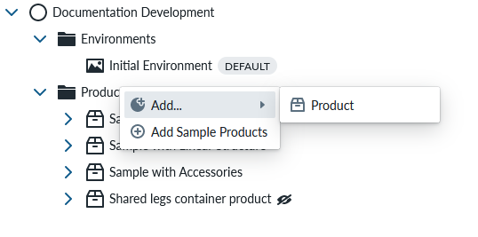
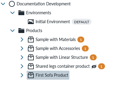
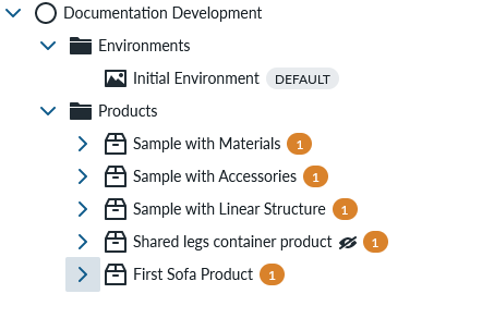
The new product Library will be empty so you will need to add sample products to it. You do that by clicking 2nd mouse button (typically the right button) on “Products” folder and selecting “Add Sample Products” from the context menu. A submenu will open with the available sample products. You can select which one you would like to be created by clicking on the corresponding submenu entry.

After the sample product(s) are loaded, you will see them in the product tree panel, something similar to the picture below:

These sample’s bring new assets into your tenant which will be helpful for you in learning. You can create a test product library for practicing and learning and this will not affect your production products which you present in the planner for your buyers.
Create your First Product into the product tree
In this tutorial, we will recreate the sample sofa product from scratch iteratively and at the end you have managed the whole creation process for a standalone and linear structure products, given this, you are able to create many other products within the application yourself.
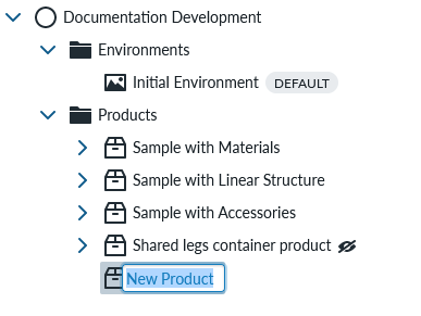
We start by creating the new product to manager where all the other configuration will be done. You do this by clicking 2nd mouse button on top of “Products” folder and selecting “Add … Product”
Name the product (while "New Product" is highlighted) to "First Sofa Product"
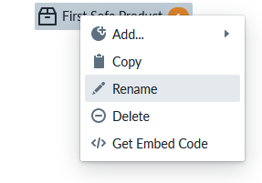
If you did not name the product for some reason, you will have the opportunity to rename your product from default immediately, but you can also rename product later by pressing 2nd mouse button on top of the product and selecting “rename”
Main product information is edited on the configuration panel and you would see a screen like this in the beginning:
The Component configuration panel changes for your new product and the name of the product is on the top. This configuration will include all top level information of your product.
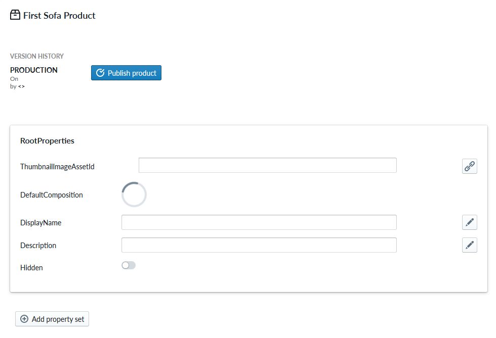
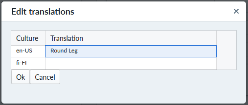
By selecting the pen icon on right you can edit the DisplayName and Description parameters noting that these parameters are localizable to many languages (see language localization for more details)
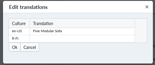
At this time, you should write “Fine Modular Sofa” to the DisplayName field and “Modular multi-part fine sofa” to the Description parameter.
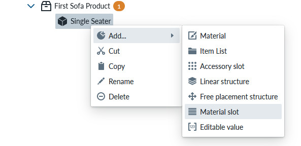
Making your 1st part of the product
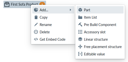
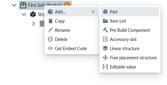
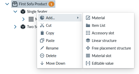
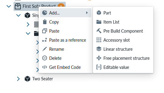
To add a module or item to the product, you click 2nd mouse button over the product name and in the contextual menu select “add… part”
A new part appears under the product tree and you should give it a name either immediately, but like the product, you can rename the part later using the contextual menu and rename operation.
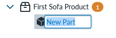
Name the part as “Single Seater” On the configuration panel you will have all the parameters that a part has:
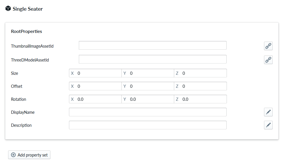
We will edit these parameters next and you should find the explanation for each parameter field in part detailed documentation. Note that if your part does not have the name you gave it (because you did rename for example), selecting something completely different product and selecting the part again, will referesh the data.
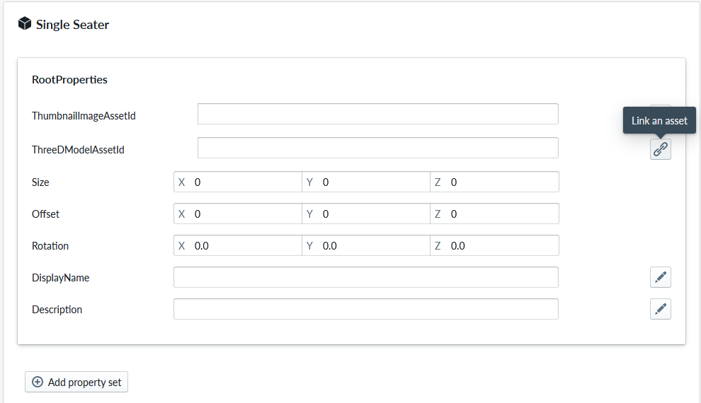
Next we should link a 3d model to the part and we do this by pressing the link icon on the ThreeDModelAssetId.
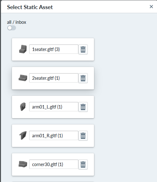
This opens asset picker and if the picker is empty, change the toggle from "inbox" to “all” to see assets
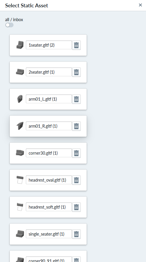
Select "1seater.gltf" which may have added characters in parenthesis as in the picture
You will see this kind of screen next:

Select the product where this part belongs in and select the part again in the product tree view to refresh the view, which now should look like this:
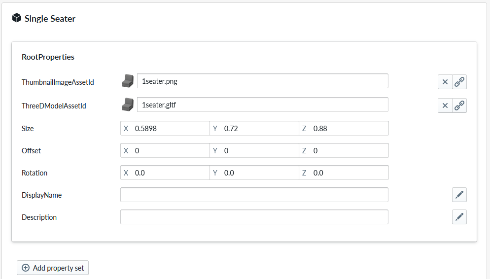
The parameters from the glTF file have been taken and a thumbnail picture and size (in meters) are listed automatically.
Edit DisplayName into “Single Seat” and Description to “Single Seat Module”
We can now press “Regenerate Runtime Products” which will allow us to test our configuration. There is a spinner that will tell when the process has completed.
After the runtime products have been regenerated, you may see errors and warnings on the product tree, like something here.
By hovering mouse over “First Sofa Product”’s yellow circle with 1 you will see the message
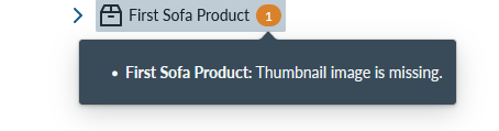
This warning indicates that we haven’t added a thumbnail to the whole product, but we will do that later and ignore it for now.
Viewing our first item
While we have selected the “First Sofa Product” the top menu has changed also for us.
By clicking on the “View ‘First Sofa Product’”
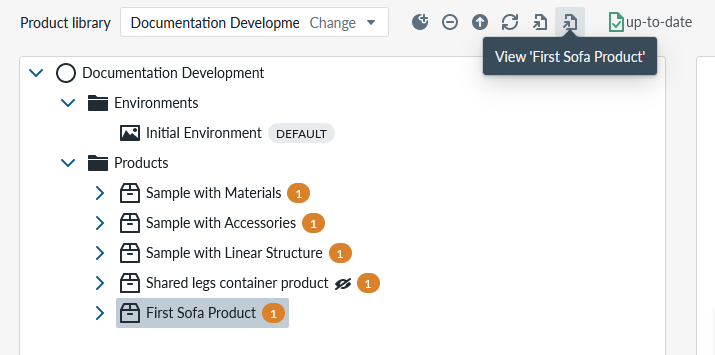
We can see the current configuration of the product in “The Planner” embedded into our Manager. Note that this product is not integrated or published anywhere, therefore you are the only one seeing it for now.
By utilizing your mouse you can rotate, zoom and pan the module, just like you would be able to do that as a customer (to rotate: move mouse while holding down left mouse button, to pan move mouse while holding down right mouse button, to zoom, move mouse up/down while holding down both left and right mouse button or use mouse center scroll wheel)
We return to the configuration by selecting Products on the left main menu
Lets continue configuring our product. Click on the “Products” on left menu, then open the configuration of “First Sofa Product” by clicking on the side arrow then select “Single Seater” item
Lets add a material to the module so that we can show how the module looks with a fabric material.
We do this by adding a Material slot from the item context menu
Note that we could add a single material by selecting the material item instead of Material slot, but we already know that this module can be purchased with different colors and materials
Name the Material slot as “Material”
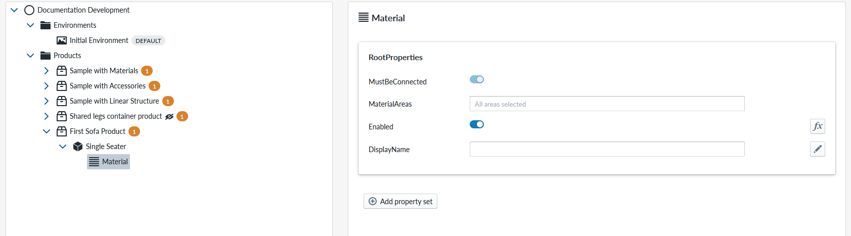
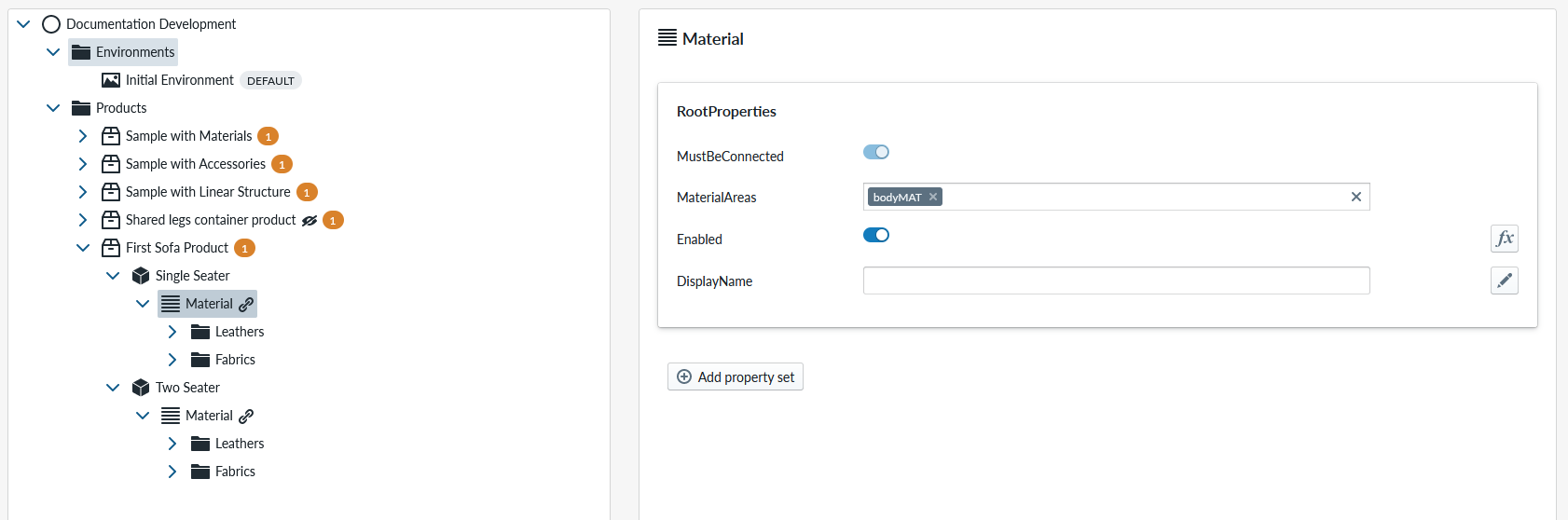
In the configuration menu, the most important part for the Material Slot is the “MaterialAreas” configuration. This allows 3d models to containing many possible “slots” for material and during the configuration selecting different material options for each material area. The sofa module has 3 material areas and the default configuration is “all areas selected” which is good for now.
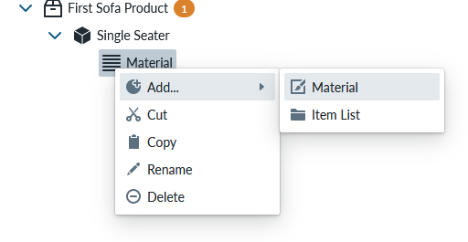
Lets then add the actual material by opening context menu for the Material Slot and selecting “add… Material”
Lets name the Material as “Fabric” for now.
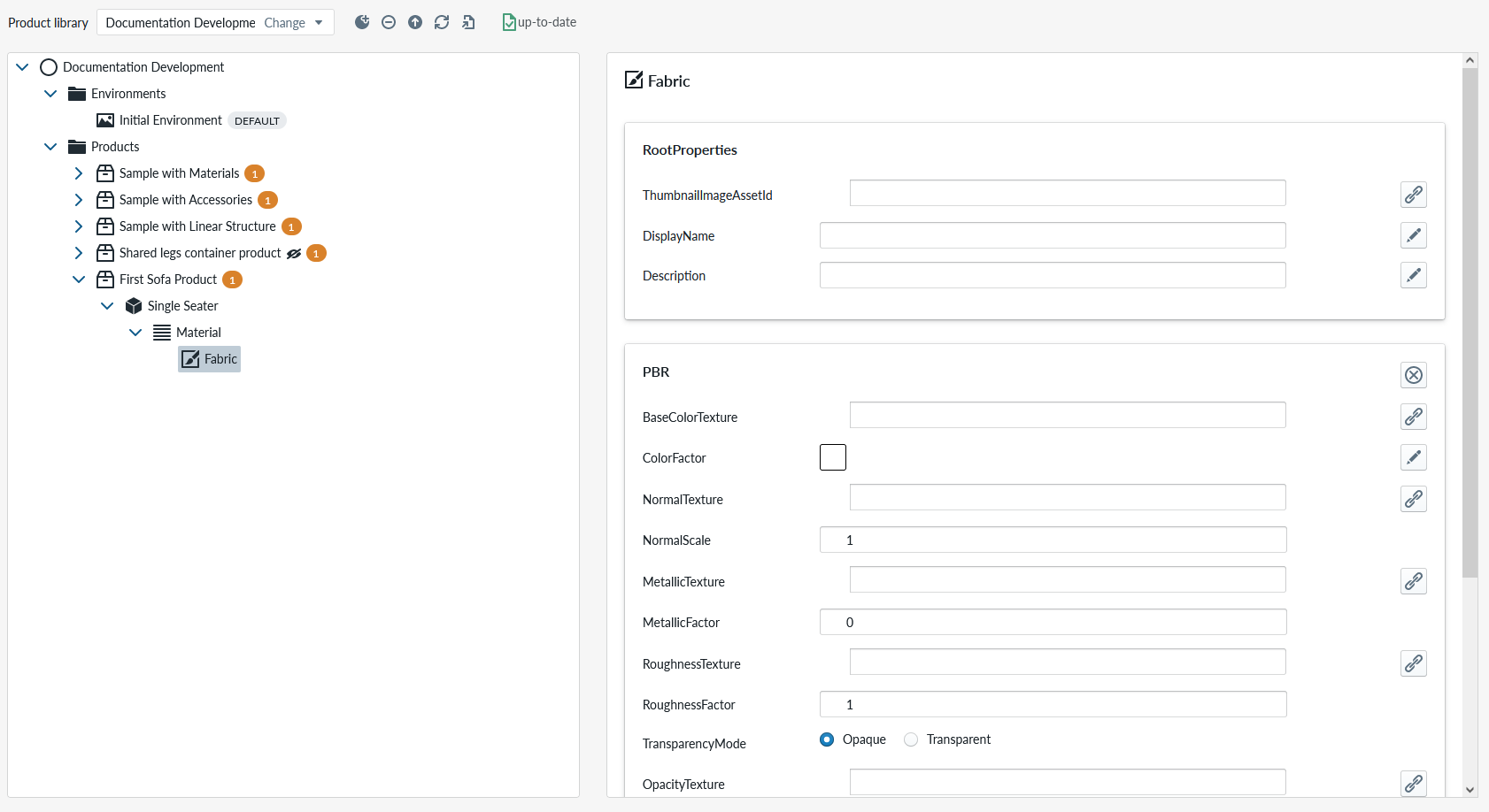
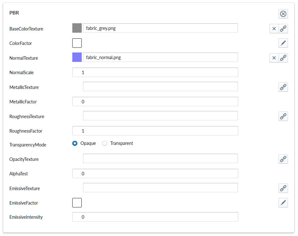
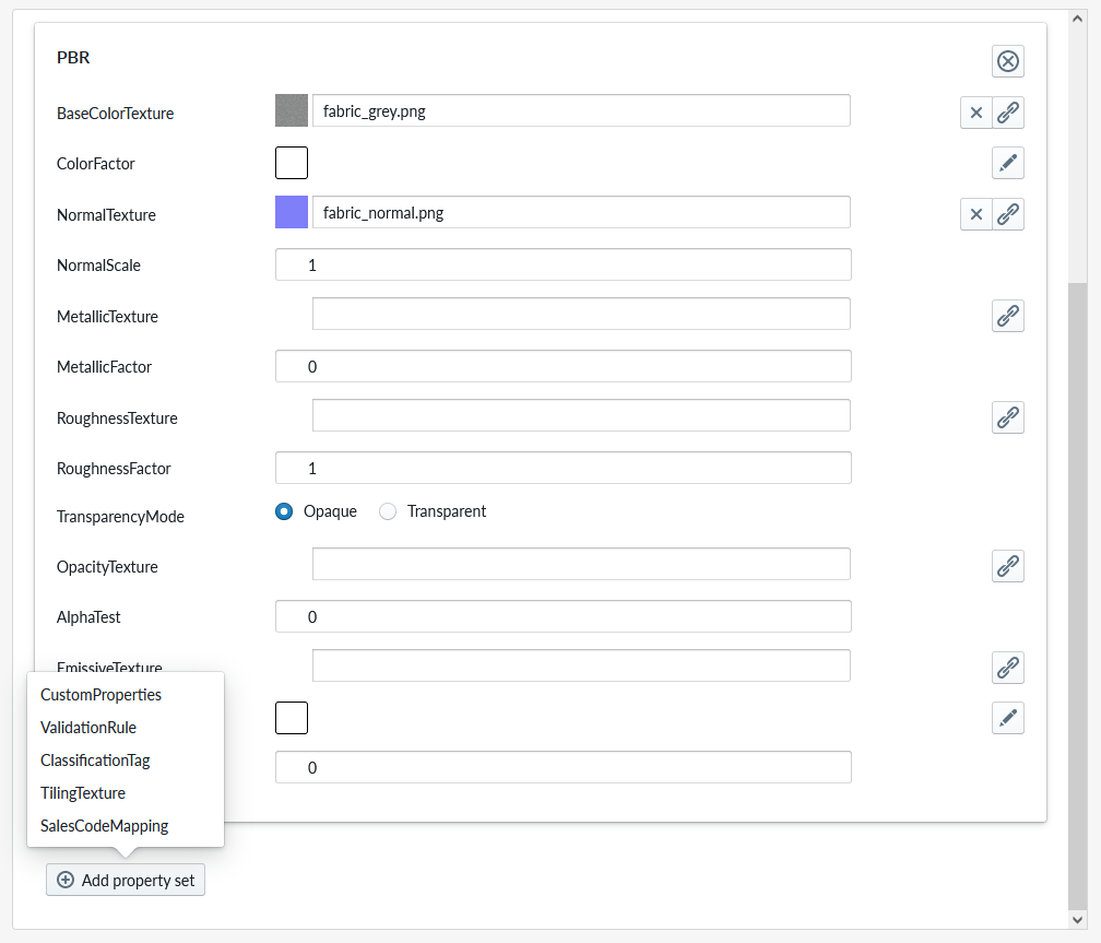
On the configuration panel, there are now many parameters. In the context of this document, we will not go through all of the parameters but the relevant ones for this product and you will find additional documentation elsewhere. The summary is that “RootProperties” are for configuring how the material is shown in the planner, “PBR” (PBR short for “Physically Based Rendering”) configured how the material is rendered. Lets configure the first fabric, by selecting “link asset” from RootColorTexture” and changing toggle to “all assets” and selecting “fabric_gray.png” (which may have a number in parenthesis) as the base texture. Then selecting “link asset” for NormalTexture and changing toggle to “all assets” again and selecting “fabric_normal.png” (again, the asset may have a number in parenthesis) Your PBR settings should look like this:
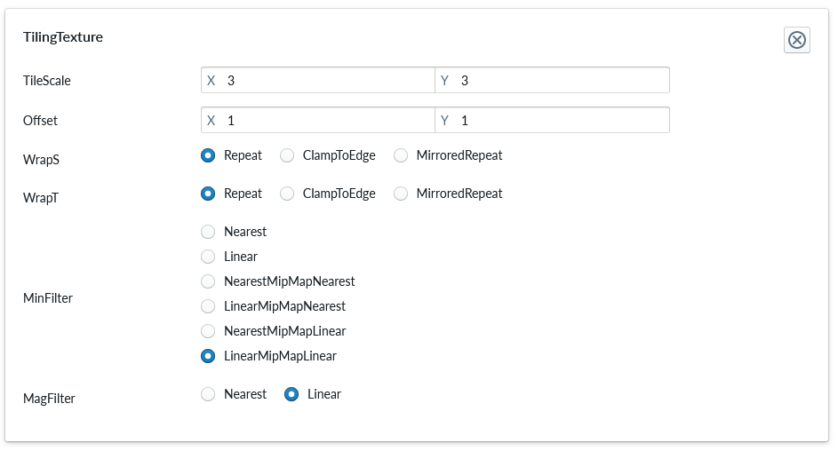
We need to add additional properties to the Material and e do that by clicking “Add Property Set” which can be found by scrolling to bottom of the configuration panel and selecting “TilingTexture” from the menu. Note that there are other property sets available as well, but these will be covered elsewhere in documentation
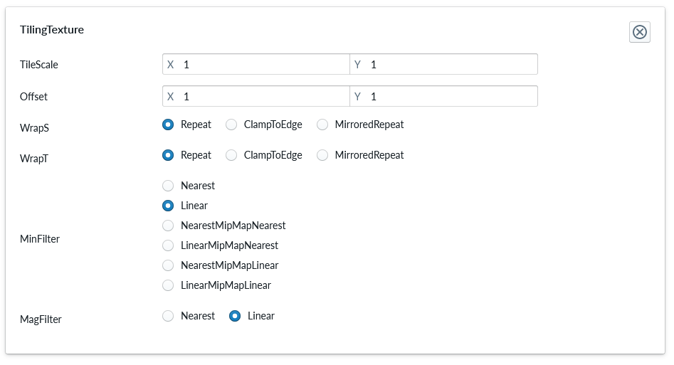
The configuration panel will reload and by scrolling to bottom of it you can see the TilingTexture Property Set.
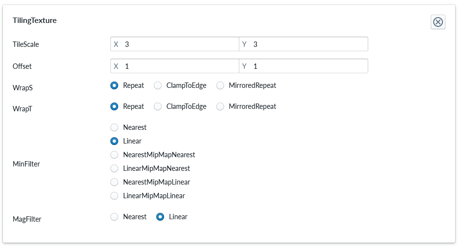
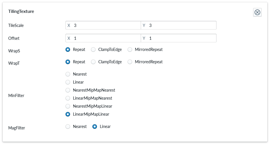
The parameters are described elsewhere in documentation and we only change the TileScale from X: 1 and Y:1 to X:3 and Y: 3. Your TilingTexture should look like this:
You can click on the “Regenerate Runtime Products” to be able to see any warnings related to how the item was build. The viewer performs anyway automatically this regenerate for you before it loads, so this manual click is optional unless you specifically want to verify the warnings/errors prior to launching the 3D view.
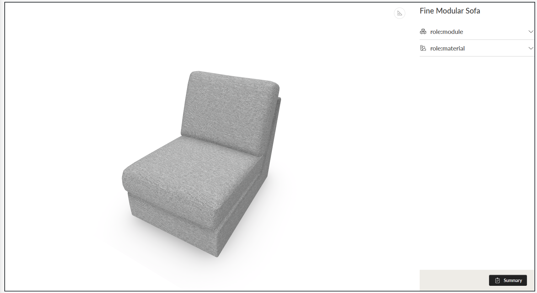
Select the “First Sofa Product” from the Product Panel and click the “View ‘First Sofa Product’” from the top menu to open the planner.
The image is a bit noisy (lots of not so nice looking rendering happening), but a gray fabric is rendered on the 3d model.
Lets change some TilingTexture parameters to make the texture rendering look better. Go back to Products, open the configuration for “First Sofa Product” and the subtree’s until you find the Mateiral “Fabric” and select “Fabric”. Scroll then down to TilingTexture Property set and change the MinFilter from “Linear” to “LinearMipMapLinear”. Your TilingTexture should look like this:
Regenerate runtime products and view the product in planner. The noise should now be gone and the fabric should look rather nice from the very beginning.
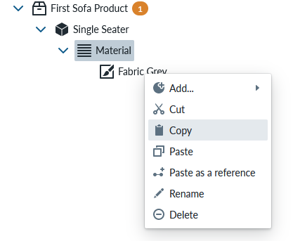
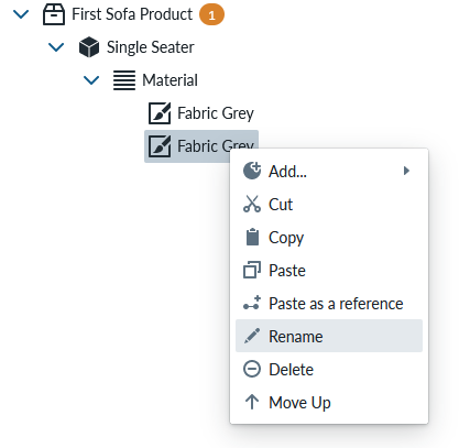
You should now rename the Fabric into “Fabric Gray” and be able to add 2 more fabrics to the item by repeating the create process, or easier by copying and pasteing a material. The following way: Select “Copy” from the context menu of “Fabric Gray”
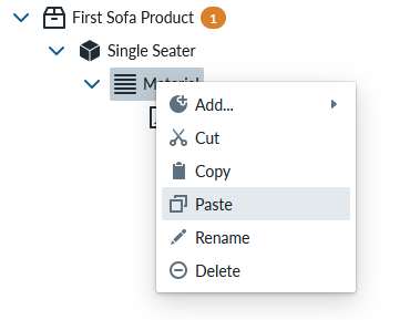
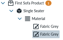
Select “Paste” in the context menu of “Material Slot”
Don’t worry about having two materials with same name now.
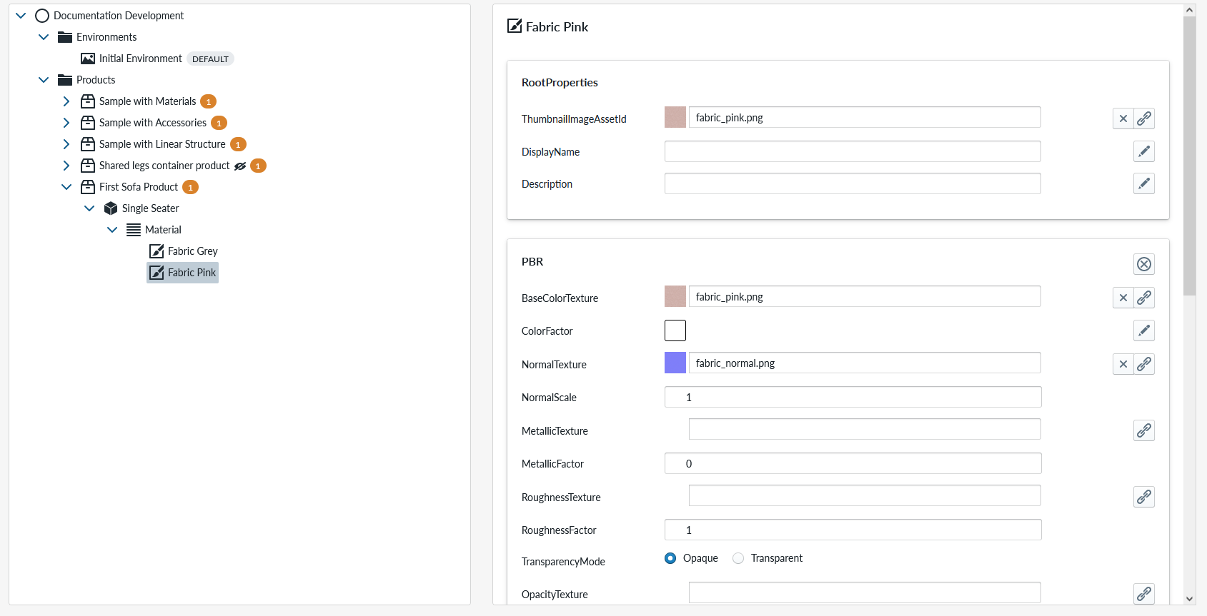
Edit the PBR Property “BaseColorTexture” by linking another asset of the lower “Fabric Gray” material and select “Fabric_pink.png”
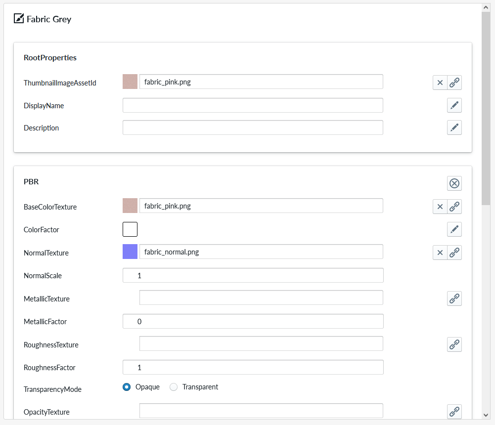 By clicking the topmost Fabric Gray and then the bottom most Fabric Gray item, your configuration panel should refresh to showing that the fabric pink is now configured as “BaseColorTexture” and “ThumbnailImageAssetId”.
You should then rename the “Fabric Gray” into “Fabric Pink”.
By clicking the topmost Fabric Gray and then the bottom most Fabric Gray item, your configuration panel should refresh to showing that the fabric pink is now configured as “BaseColorTexture” and “ThumbnailImageAssetId”.
You should then rename the “Fabric Gray” into “Fabric Pink”.
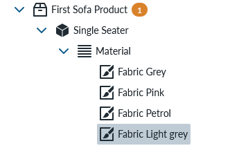
Repeat the process to create “Fabric Petrol” and “Fabric Light grey”. Your Product panel should look like this after the process:
Lets also create few Leather fabrics and while the process is very similar to the cloth fabrics, there is few changes that need to be done. Lets start by creating new Material and call it “Leather Yellow”. In the PBR Property Set, select “leather_yellow.png” from asset library for BaseColorTexture, “leather_normal.png” for NormalTexture and “leather_roughness.png” for the RoughnessTexture. Change NormalScale parameter from 1 to 1.5 and RoughnessFactor from 1 to 0.55. Your PBR Property Set should look like
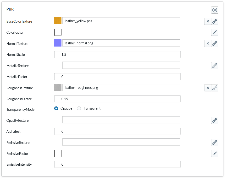
Add also the “TilingTexture Property Set” and change the previous parameters to get to the following configuration:
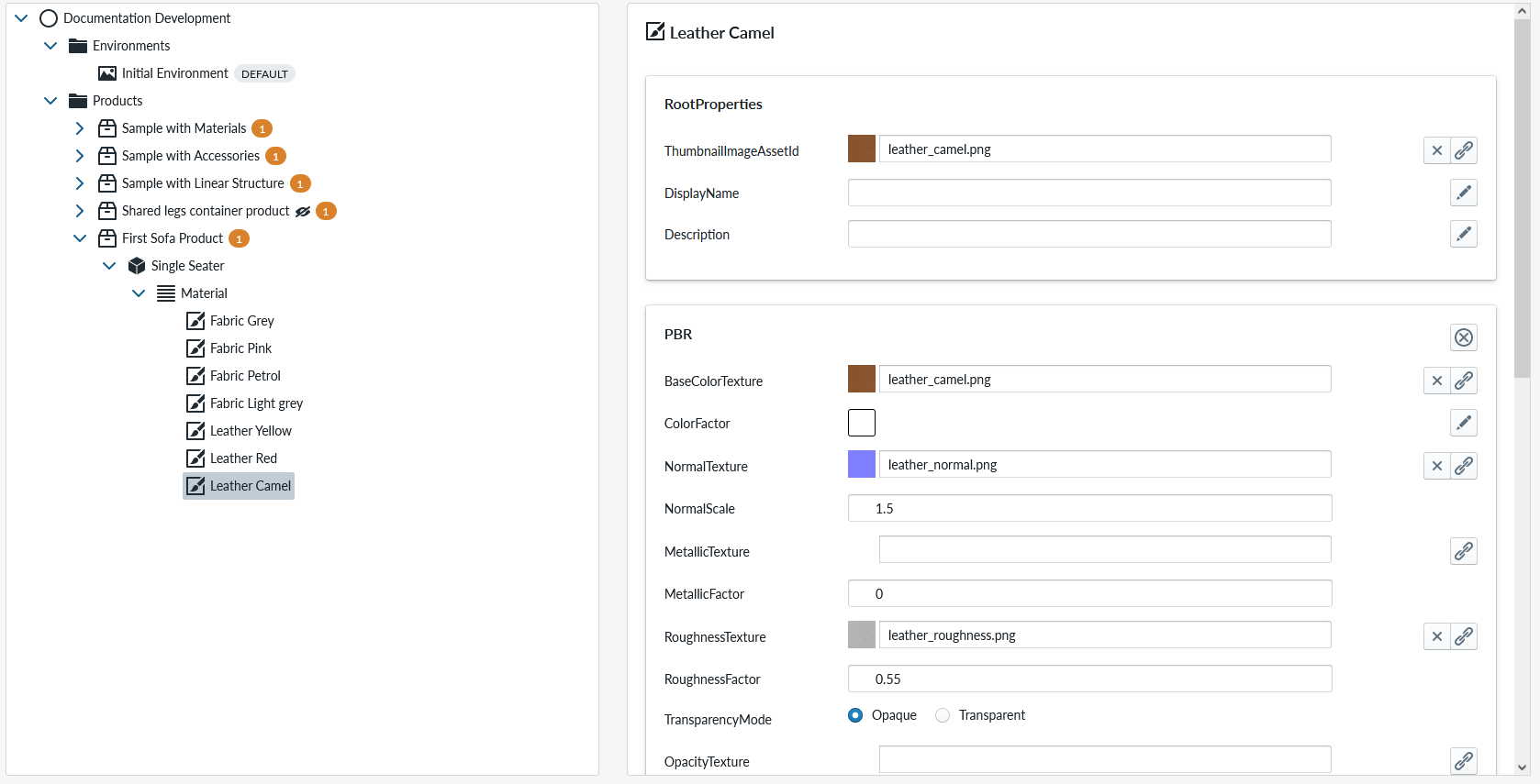
Copy-paste the leather product into 2 new material and edit these for “Leather Red” and “Leather Camel” by changing the BaseColorTexture into assets “leather_red.png” and “leather_camel.png”
You can regenerate the runtime products and test your configuration now.
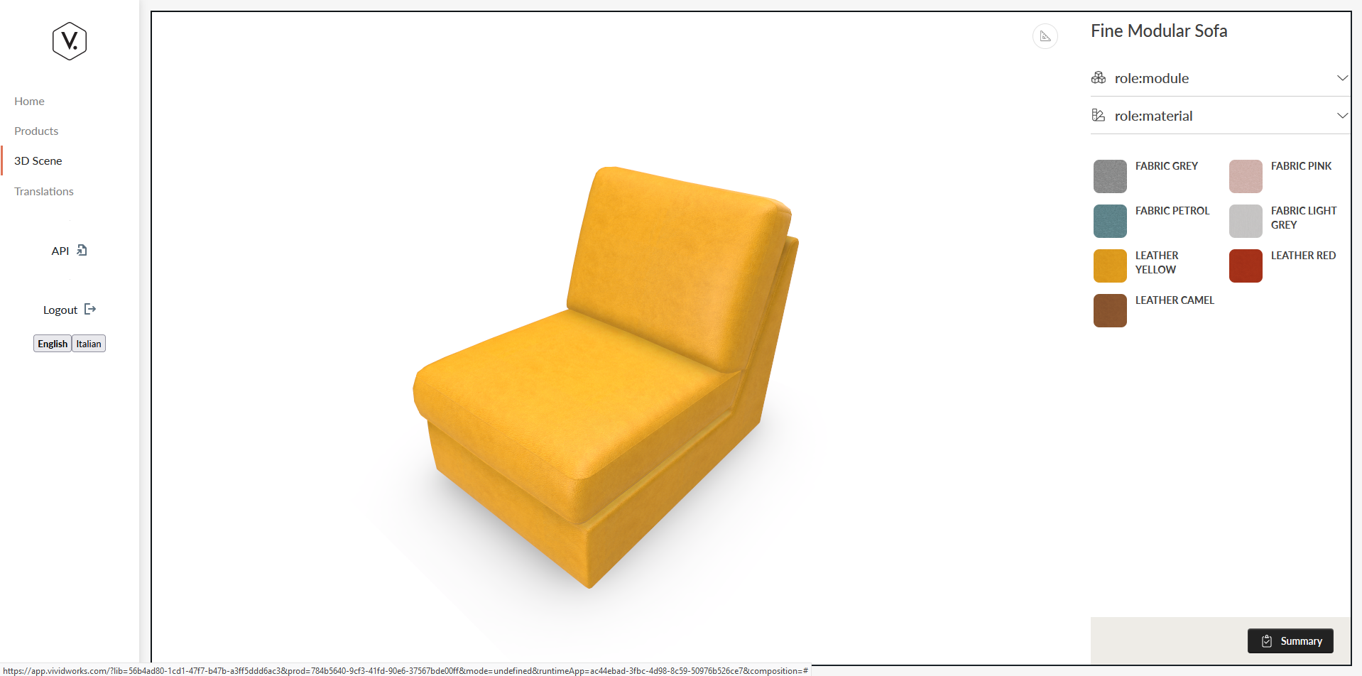
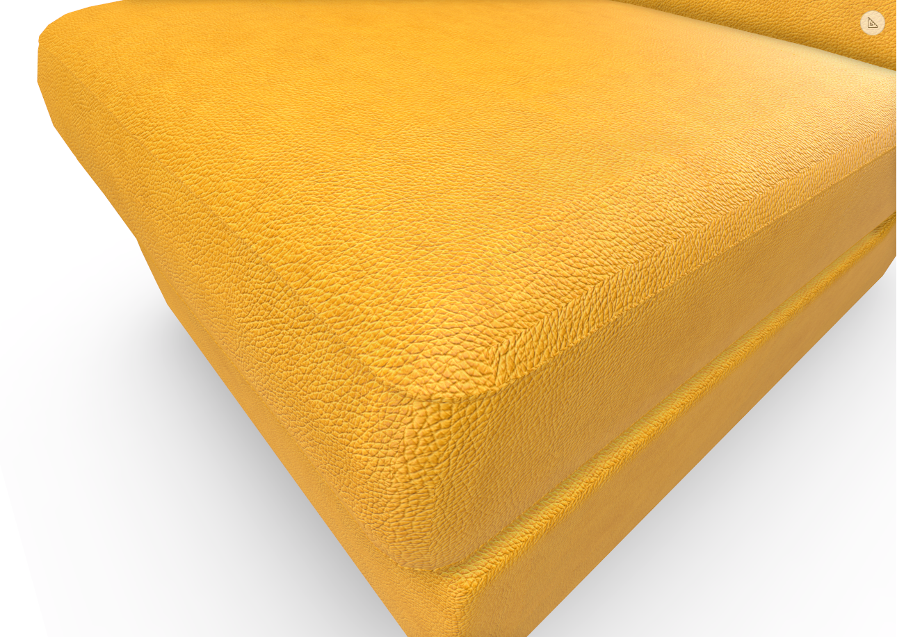
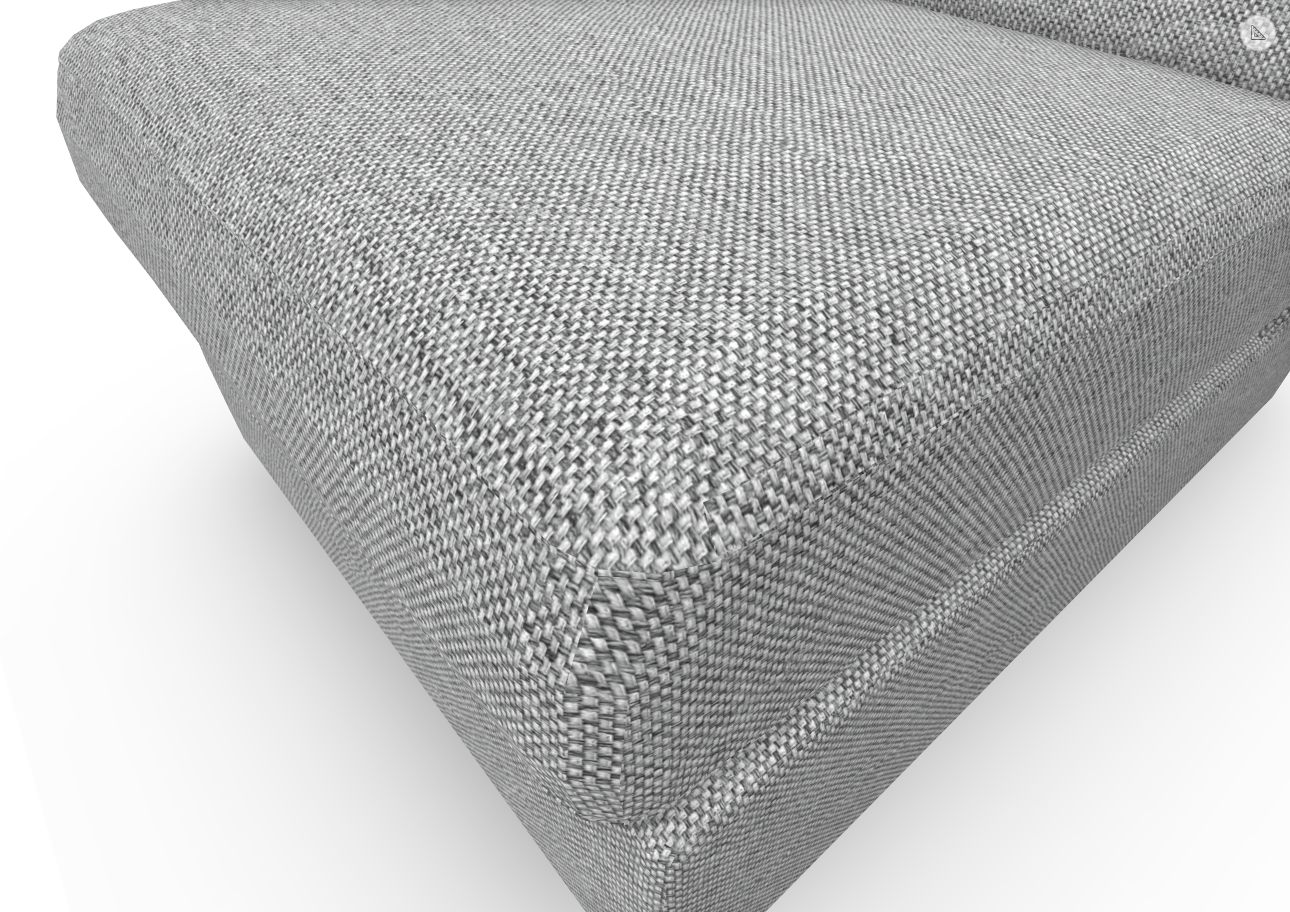
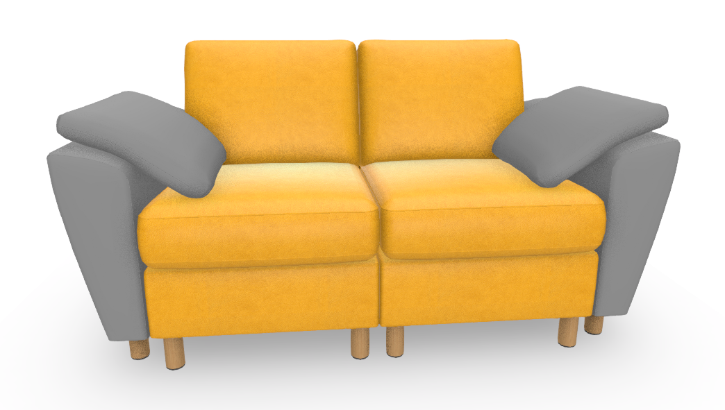
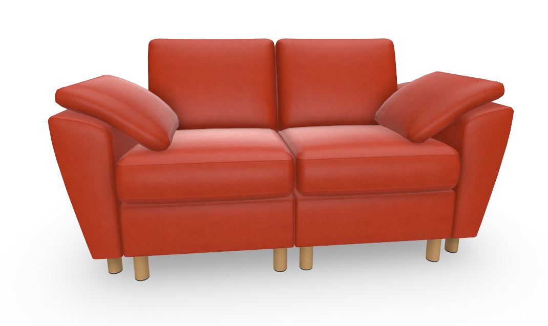
By selecting material submenu and eg. Leather Yellow, you should see the module with different textures. Note that textures are loaded only when you select, so the first load might take a while.
You can check visual quality by zooming in closer. Here are 2 screenshots from the test configuration
Next we will separate the material to fabrics and leathers. This is achieved by adding an Item List to the Material slot for each Material category
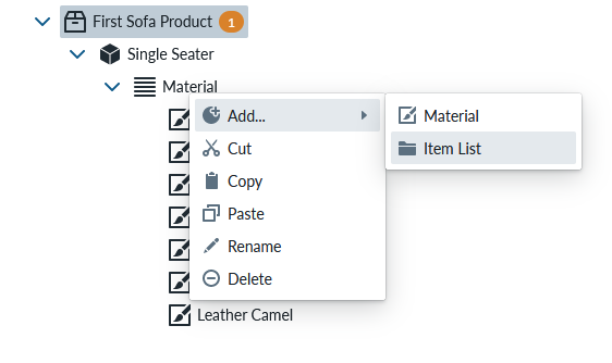
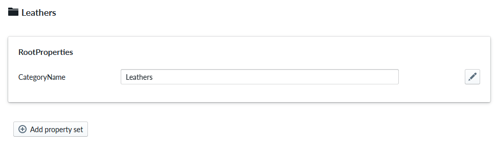
Create two Item Lists, one named “Leathers” and another “Fabrics”
Change the CategoryName for each Item List to the same as the Item List name here. Below is example for Leathers Item List
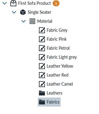
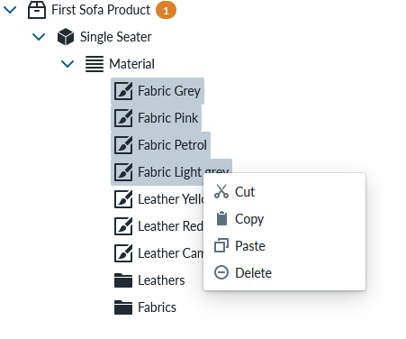
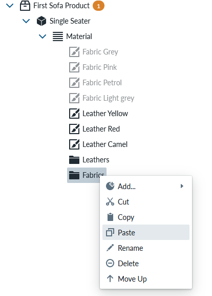
Then we can cut and paste the Material into the right Item List group. While pressing CTLR button down and clicking each fabric in the list we can select the 4 of them and when opening the context menu, we can cut them and paste them into the Fabrics Item List
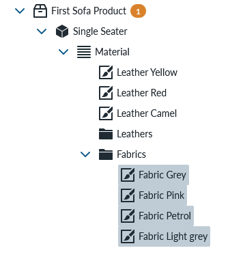
Select all 3 leathers and cut-paste them into the Leathers Item List Your product panel should look something like this:
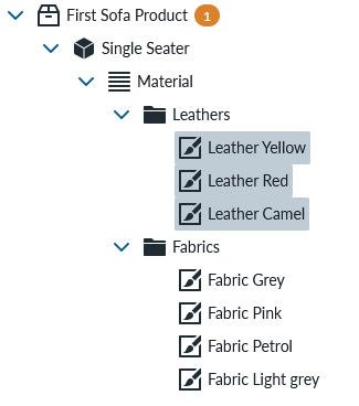
Regenerate the runtime products and open the product view to planner.
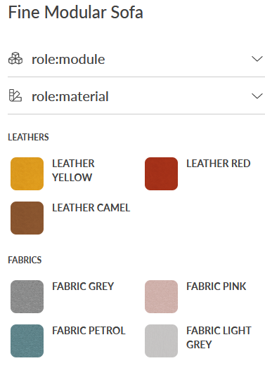
The menu is not ideal as the titles are note localized correctly. Lets change this next. Return to the products view and select the “First Sofa Product” from the products panel
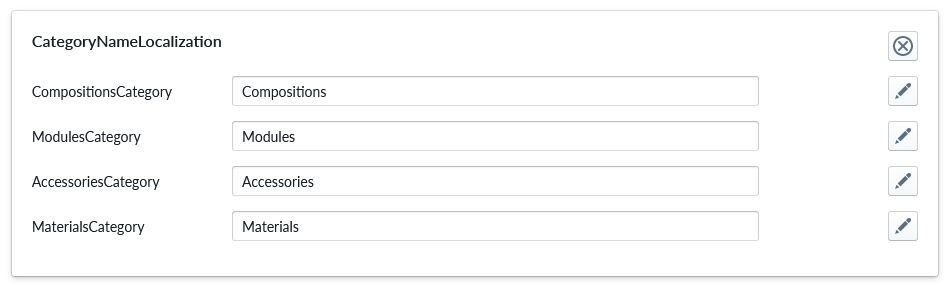
We are going to add CategoryNameLocalization Property Set from the configuration panel of the product view:
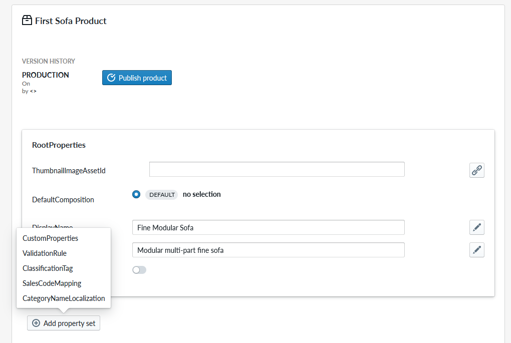
This will add the property set and our view changes to
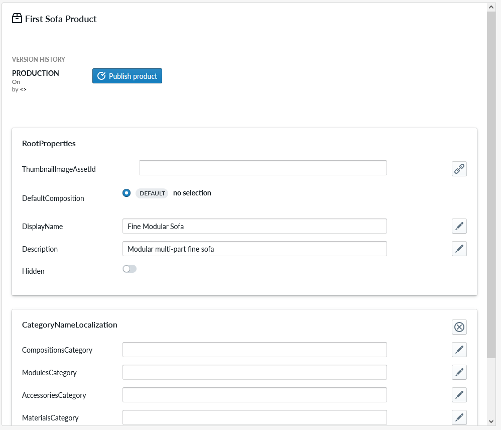
Edit the categories so that it reads as follows:
 Recreate runtime products and open planner view for the product
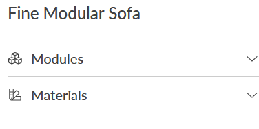
The categories we see have now a much more nicer name. Don’t worry about not seeing the two other categories at this time. Return to the products view
Add another module
So far we have only worked with one module of a modular sofa, so lets add another module. We do this bt opening context menu for the product and selecting “add… part”
Name the part as “Two seater”
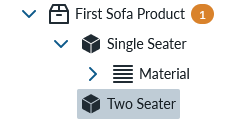
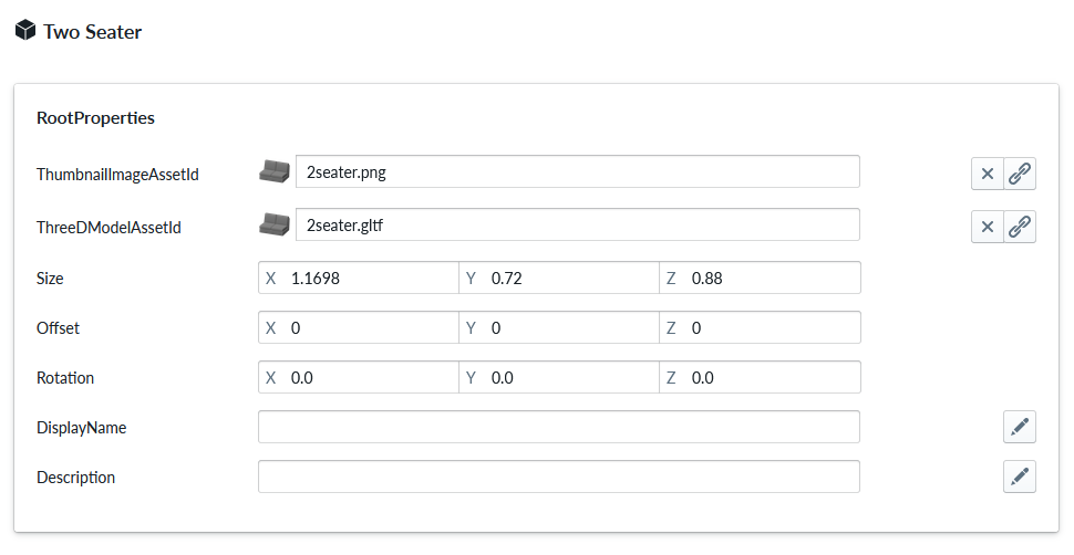
From the “Two Seater” configuration panel for “ThreeDModelAssetId” link an asset from asset inventory named “2seater.gltf”
Click the Single Seater item and click the Two Seater item to see the updates Two Seater configuration in the configuration panel.
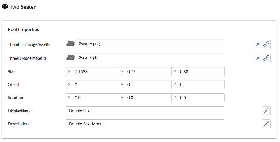
Edit the DisplayName to “Double Seat” and Description to “Double Seat Module”
We would like to have the same material for this item as well and we could achieve it manually creating the same work that we did already for the Single Seat Module again. We could also copy paste the material slot and its elements, but the disadvantage of that is that we would need to copy all the new fabrics and changes across all the items. There is a better way to manage material for items that share them.
You should select the Material Slot of the Single Seater Module and select copy.
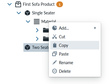
Instead of “paste” to the Two Seater Module, you should select paste-as-a-reference.
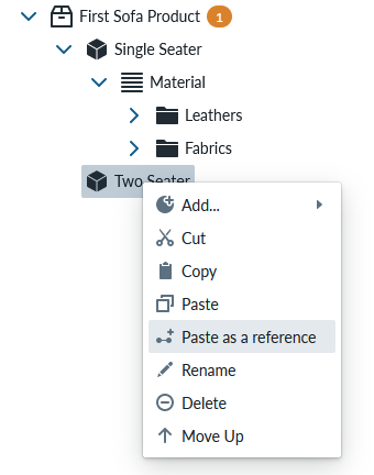
This creates a link between the two items in a way that if you edit the contents of the Material slot, all items which this Material slot is linked to (through paste as a reference) will see the same edits.
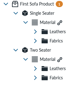
An easy test would be to eg edit the material slot under Single Seater to only touching one material area and seeing that the same change has become effective in Two Seater’s Material Slot as well
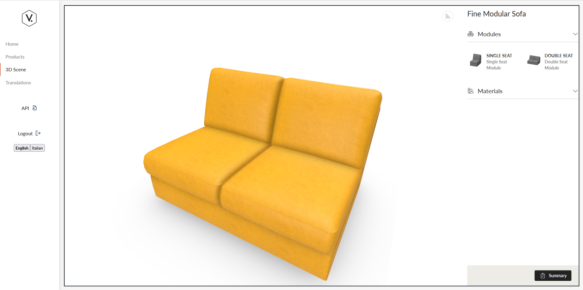
Make sure that the MaterialAreas selection is changed back to “all areas selected” and regenerate the runtime products and open the planner.
We can now select Single Seater or Double Seater, but only one at a time in the planner.
Lets switch back to the products view and continue editing the product. Next step is to add legs to the sofa elements.
Add accessories to modules
Legs are child parts of the main item and are added in as “accessory slot” items. You can add an accessory slot by opening the context menu for the item and selecting “add … accessory slot”
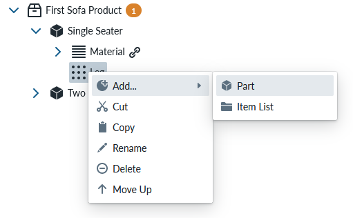
Name the accessory slot as “leg” for now. In order to define what part is put into the accessory slot, ope the context menu of the accessory slot (with clicking right mouse button over the Accessory slot item) and selecting “add… part”
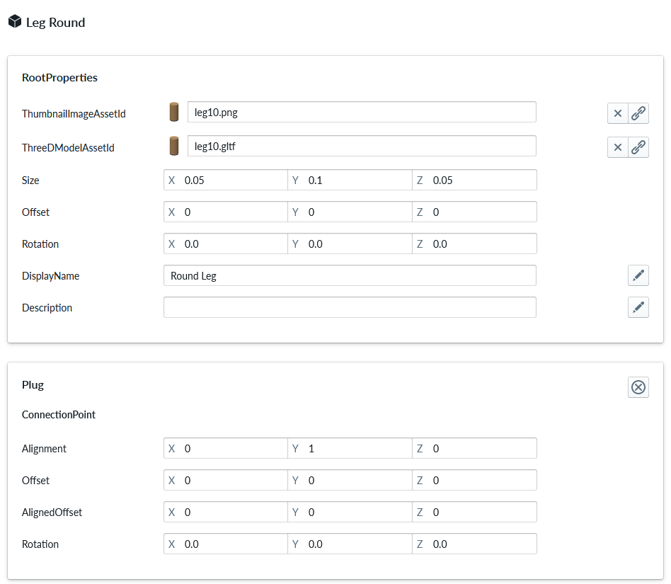
Name the part as “Leg Round”. Your view contains now accessory part configuration on the configuration panel.
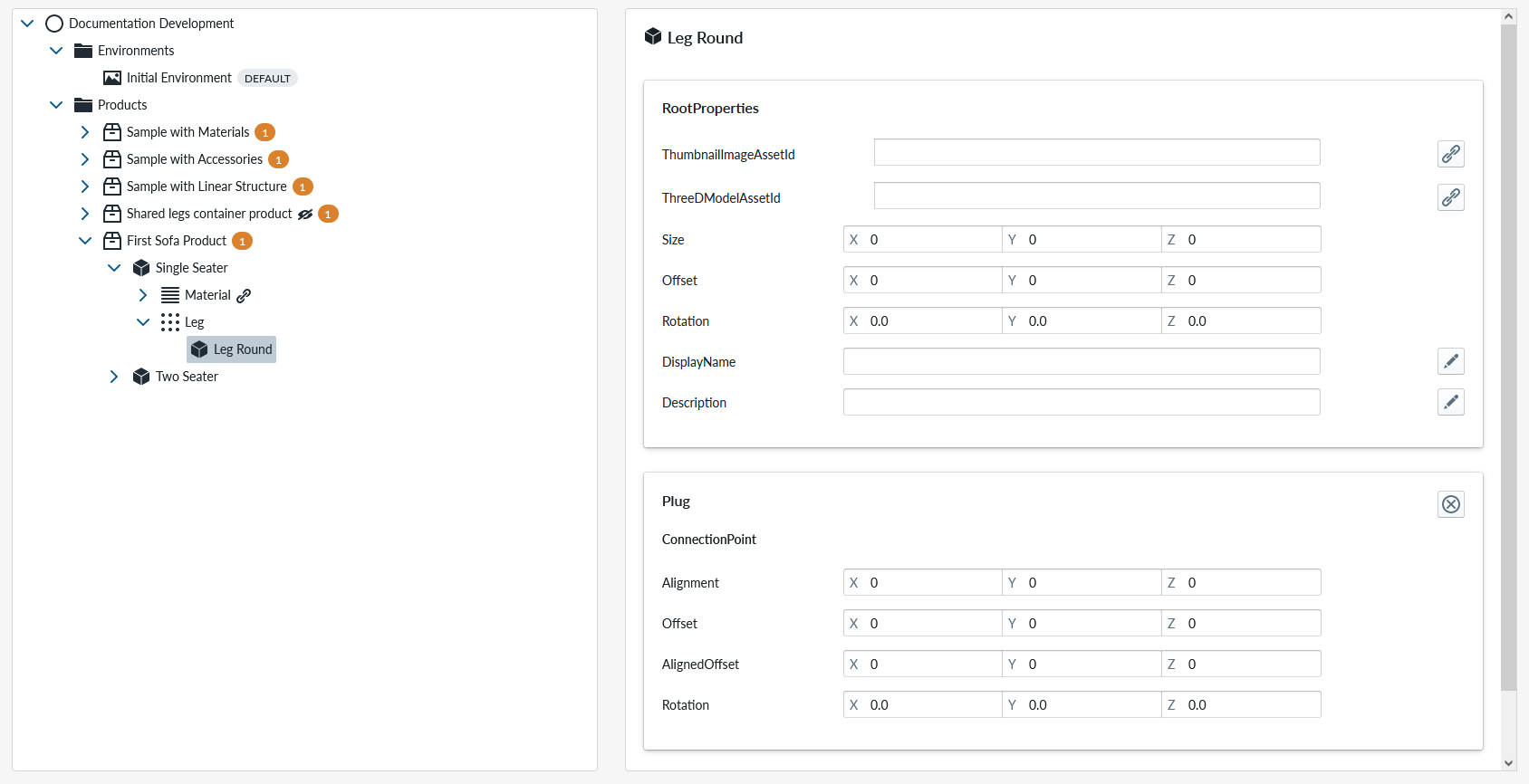
Link the “leg10.gltf” asset from the asset picker to this part from the link an asset button of the “ThreeDModelAssetId”. You may have to scroll down the asset picker to find it. Change the DisplayName to “Round Leg”.
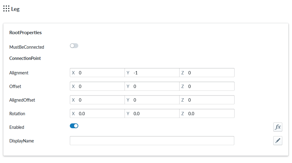
As this is a part, we need to configure it’s position in relation to the item it is an accessory to. We do this by editing the parameters of the accessory slot. The alignment parameter is used to define which surface of the 3d model we are attaching items. We want to put the leg under the Single Seater product.
(X dimension is the left and right surfaces of the model, Y is the top and bottom surfaces and Z is the front and back surfaces)
So in order to do that, we must configure alignment of the Accessory slot with Y: -1 and turn on “MustBeConnected” which indicates that this accessory cannot be unconnected from the “owning item”
and the alignment of the leg part as Y: +1 for the plug property set
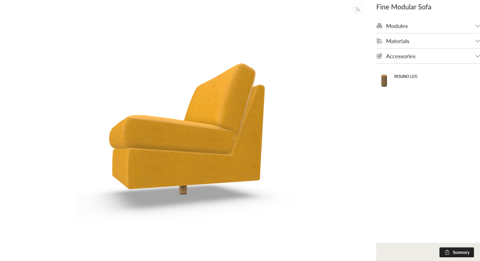
This configuration basically means “connect the top of the leg to the bottom of the module”. Regenerate runtime products and open planner and select the Single Seater module and add the accessory leg from the accessory menu.
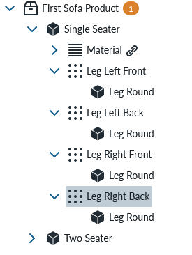
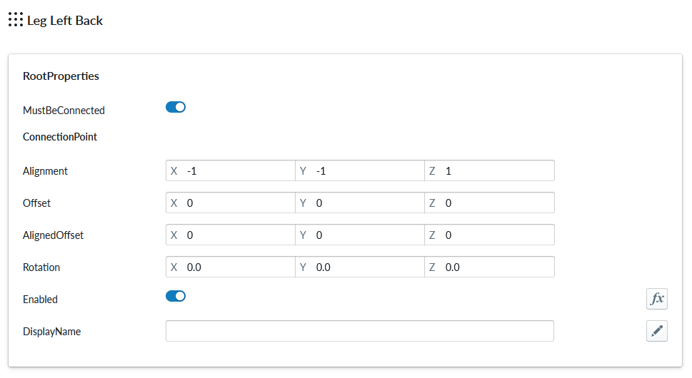
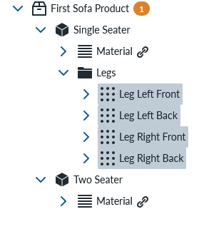
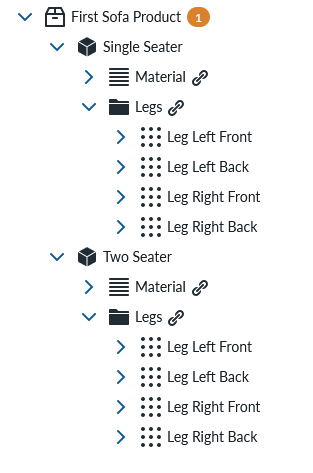
This is not entirely enough for us, so we still need to add few more things as configuration for the leg accessory to work properly as we need 1 leg in each corner of the module. Return to the products view and make 3 more Accessory slots for the Single Seater by copy-pasting the Leg slot and rename all four so that you have “Leg Left Front”, “Leg Left Back”, “Leg Right Front” and “Leg Right Back”. Your product tree should look like this:
Lets also add a Item List to the Leg Left Front called “Legs” and move the Leg Round part into the Item List.
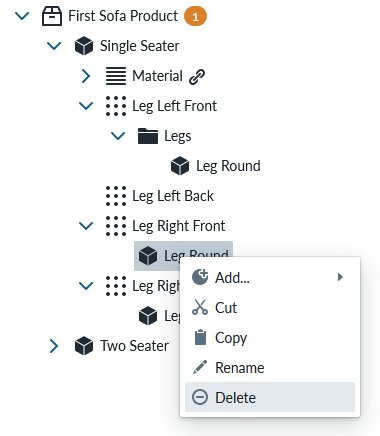
Delete the Leg Round from the other accessory slots by opening context menu of the leg and selecting Delete
Copy the Item List “Legs” from the “Leg Front Left” and paste it as reference to the 3 other accessory slots.
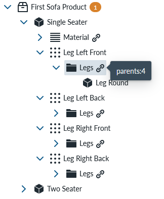
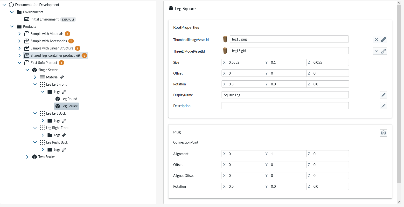
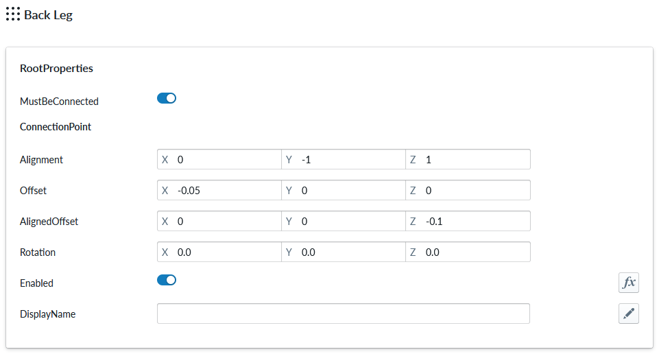
When your mouse hovers over any of the Legs Item Lists you should see that there are 4 parents which means that the leg is a shared configuration for all 4 accessory slots. Before we configure the leg positions, lets add another leg item into the legs Item List by opening context menu for the “Legs” Item List and seleciting “add… part” and lets call the part “Legs Square” add the 3d model “leg15.gltf” from the asset picker and add in Plug Property Set and change the Alignment property Y: 1 Your Leg should look like this when configured:
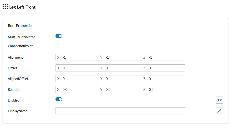
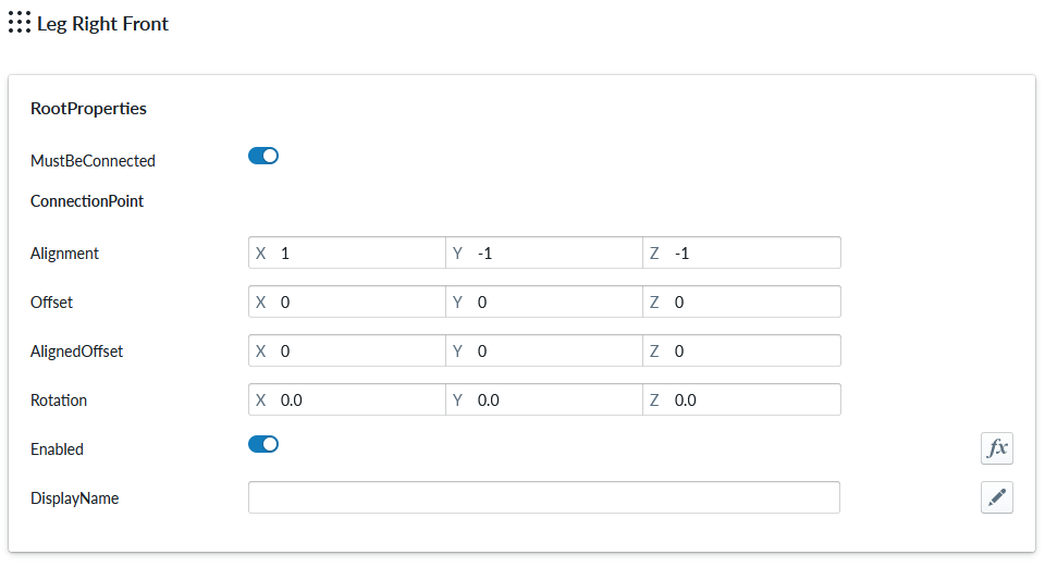
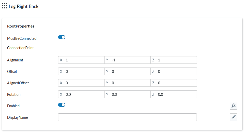
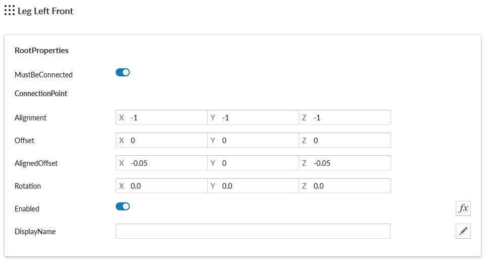
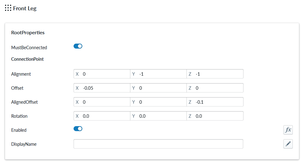
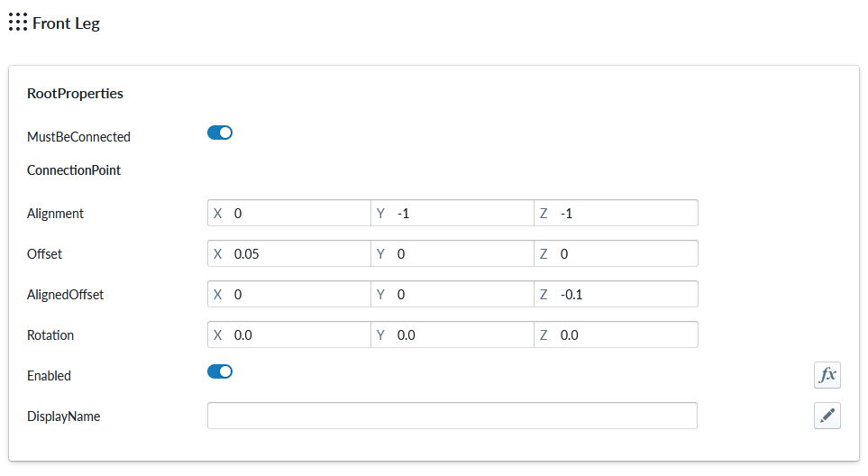
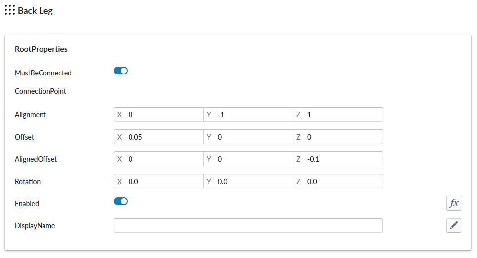
In order for us to configure the leg positions properly we need to also configure the material slots properly. For the left legs we must set the alignment property X: -1 and right legs X:+1 and Front legs: Z: -1 and back legs Z: +1 and Y:-1 for all legs. Addionally set “MustBeConnected” as “on” so that there will always be a leg under the module. Left Front Leg should look like:
The other Legs should look like:
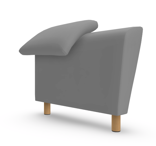
Regenerate the runtime products and open the planner. Uups, the legs appear in the right place, but incorrectly aligned under the module:
In order to align the accessory slot properly, we need to adjust the alignment of the slot position relative to the model they are connected to. This is done using the “AlignedOffset” parameter of the Accessory slot. Lets first do this for the Left Front Leg. Aligned offset with negative values move the accessory slot closer to the center of the parent model and positive values move away from the center. By changing the alignedOffset X: -0.05 and Z: -0.05 we move the leg under the module.
Regenerate the runtime properties and open the planner.
Lets change the parameters for the other legs as well:
| Leg | X | Y | Z |
|---|---|---|---|
| Right Front Leg | -0.05 | -0.05 | |
| Left Back Leg | -0.05 | -0.1 | |
| Right Back Leg | -0.05 | -0.1 |
Regenerate the runtime products and open the planner
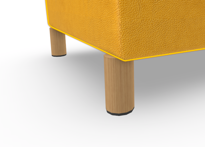
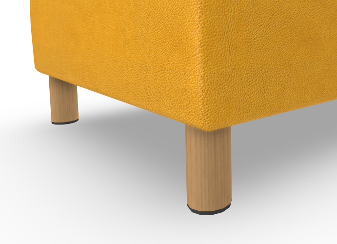
We needed to move the back legs a bit more in the Z dimension to get the under the chair.
Regenerate runtime products and open the planner
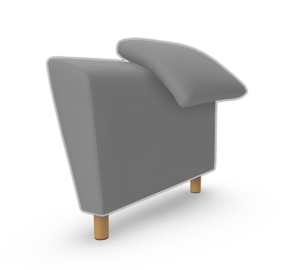
Close inspection of the front legs show that they are not entirely under the module and by adjusting the Z of both front legs to Z: -0.07 we get the nicely under the model:
Add the legs to the other module
The Two Seater product does not yet have legs attached, so next step is to change our configuration so that we get legs for it too. Again, we could create all the configuration manually, but as the configuration shares the basic properties, we will utilize the paste-as-reference model again, by first making and Item List under the Single Seater product and cut-pasteing the leg configuration under it, lets call the Item List “Legs”
Then lets copy and paste-as-a-reference the Legs Item List to the Two Seater item.
Regenerate the runtime products and open the planner and select the two-seater module
Now the two seater sofa has legs as well. Our configuration was quite easy as the legs are placed under the module in a easily configurable way, the Alignment and AlignedOffset worked in our favour in this model as the legs are placed in the same manner from the bounding box of the model point of view. We would have had a more challenging task to work with “Offset” parameter of the AccessorySlot as a alternative to the “Alignment” and “AlignedOffset” that work together.
Making the sofa modular
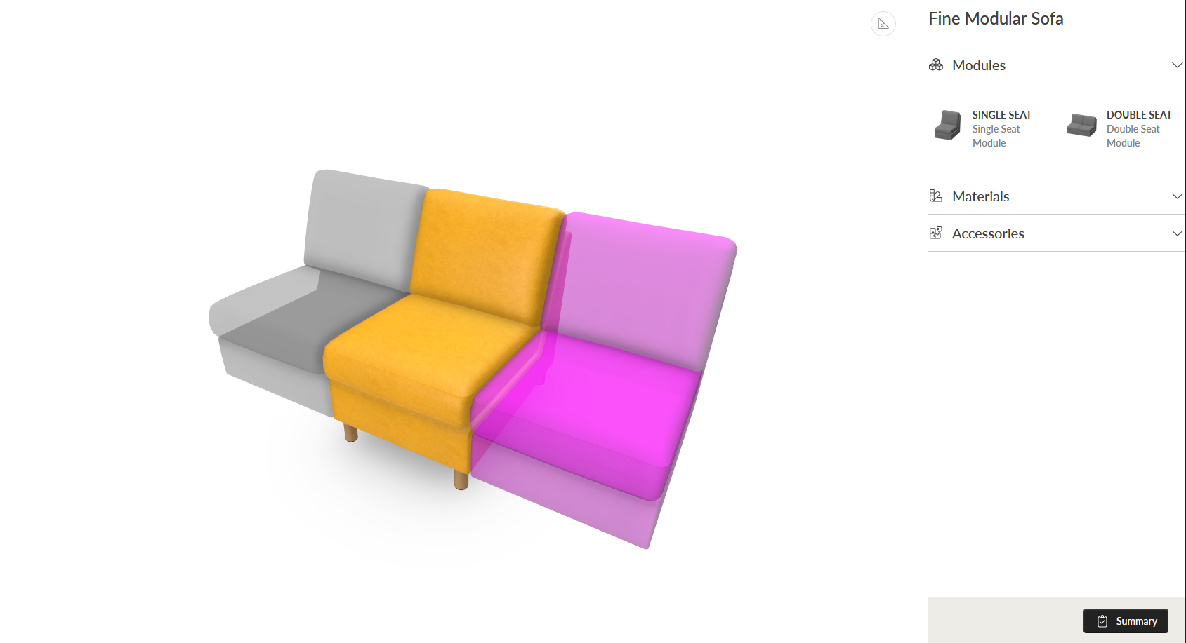
You can play around with changing the module, materials and accessories and enjoy your configuration work, but we have few more things to do before we can launch the product. One thing is that this is a modular sofa, and we should be able to have the two modules attach to each other to form a longer sofa.
We do this via “a structure” and we start by adding a structure rule to the product, by opening context menu of the product and “add… Linear Structure”
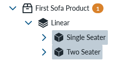
Name the structure as “Linear” and cut the parts and paste them under the linear structure.
Regenerate the runtime products and open the planner
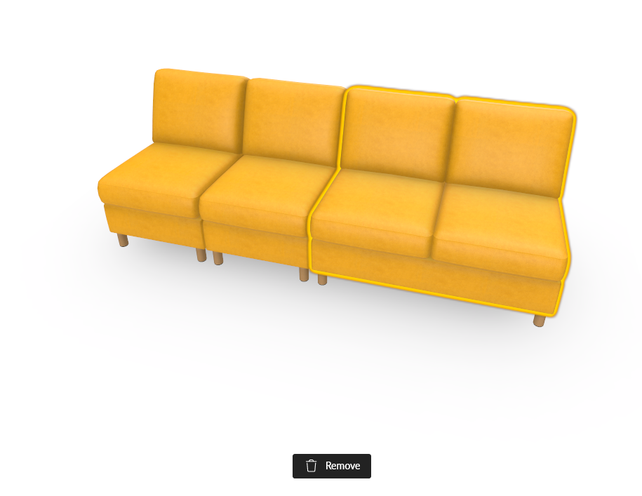
You can now add either module freely.
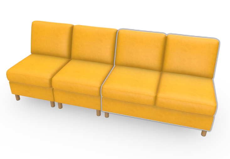
By selecting one module, you will see remove button and be able to remove an item from the view.
There is a tiny gap between the item, visible eg if you choose two Single Seaters and change the Red Leather material and view the sofa directly from the front.
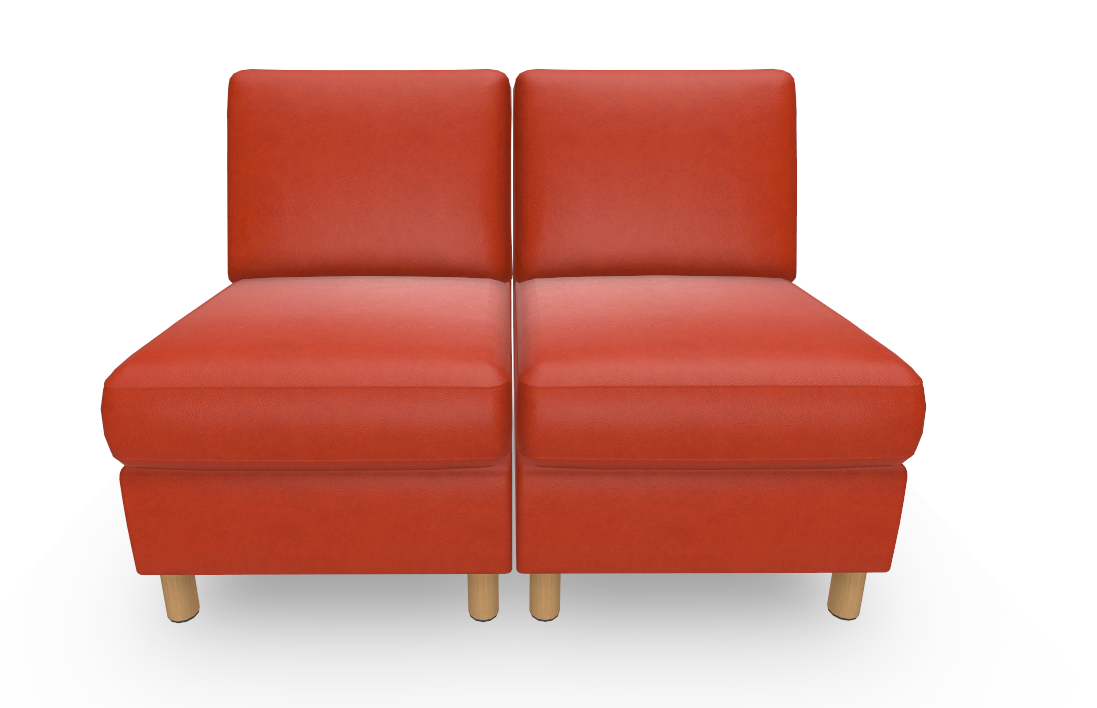
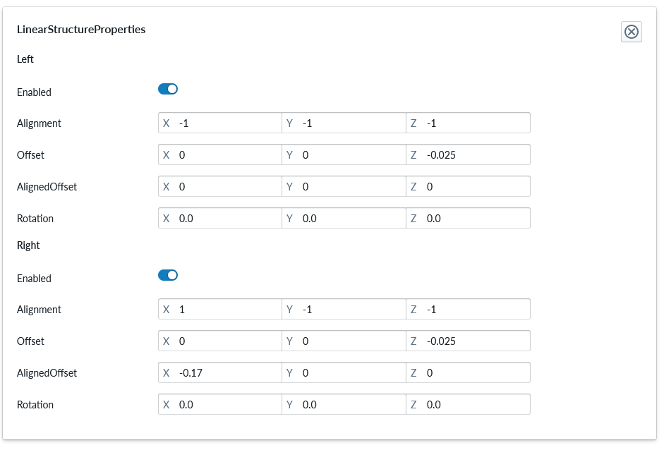
This can be fixed with adding a Structure specific property set called “LinearStructureProperties”
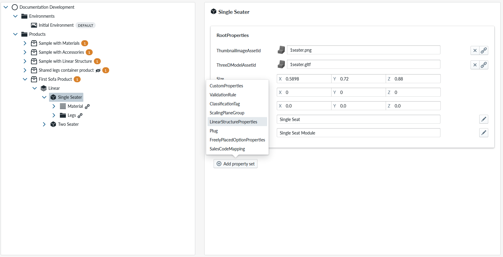
The configuration panel now has a new property set:
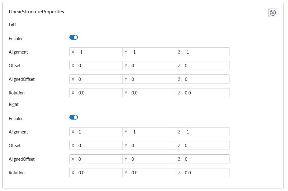
The property set contains parameters for “the left side” and the “right side” of the part. And the parameter AlignedOffset allows us to adjust how the part aligns with the neighbouring element both on the left and right side. Lets change the X: in both to X: -0.002
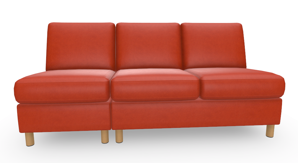
Do this for both parts of the product and regenerate runtime models and open planner to see that the gap has disappeared.
Add armrest modules
Next, lets configure arm rests.
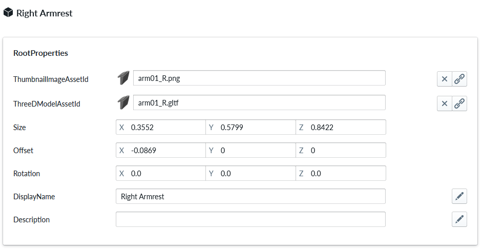
We do this by adding in parts under the Linear Structure. Lets make “Left Arm Rest” and use asset “arm01_L.gltf” and Right Armrest and use asset “arm01_R.gltf”
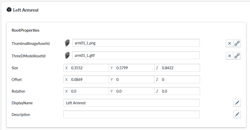
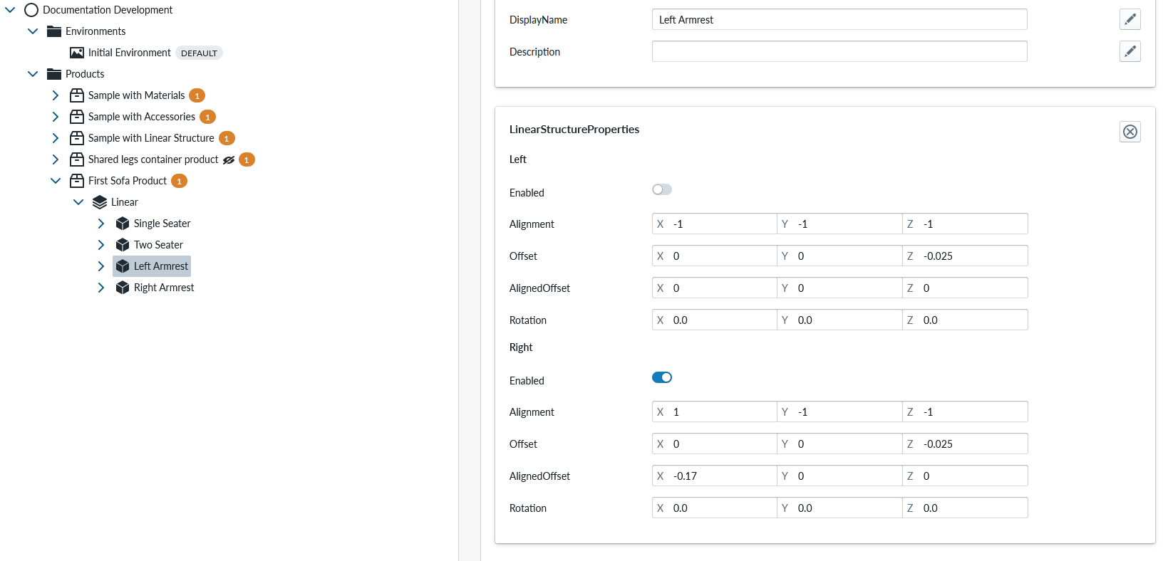
The left armrest configuration should look like:
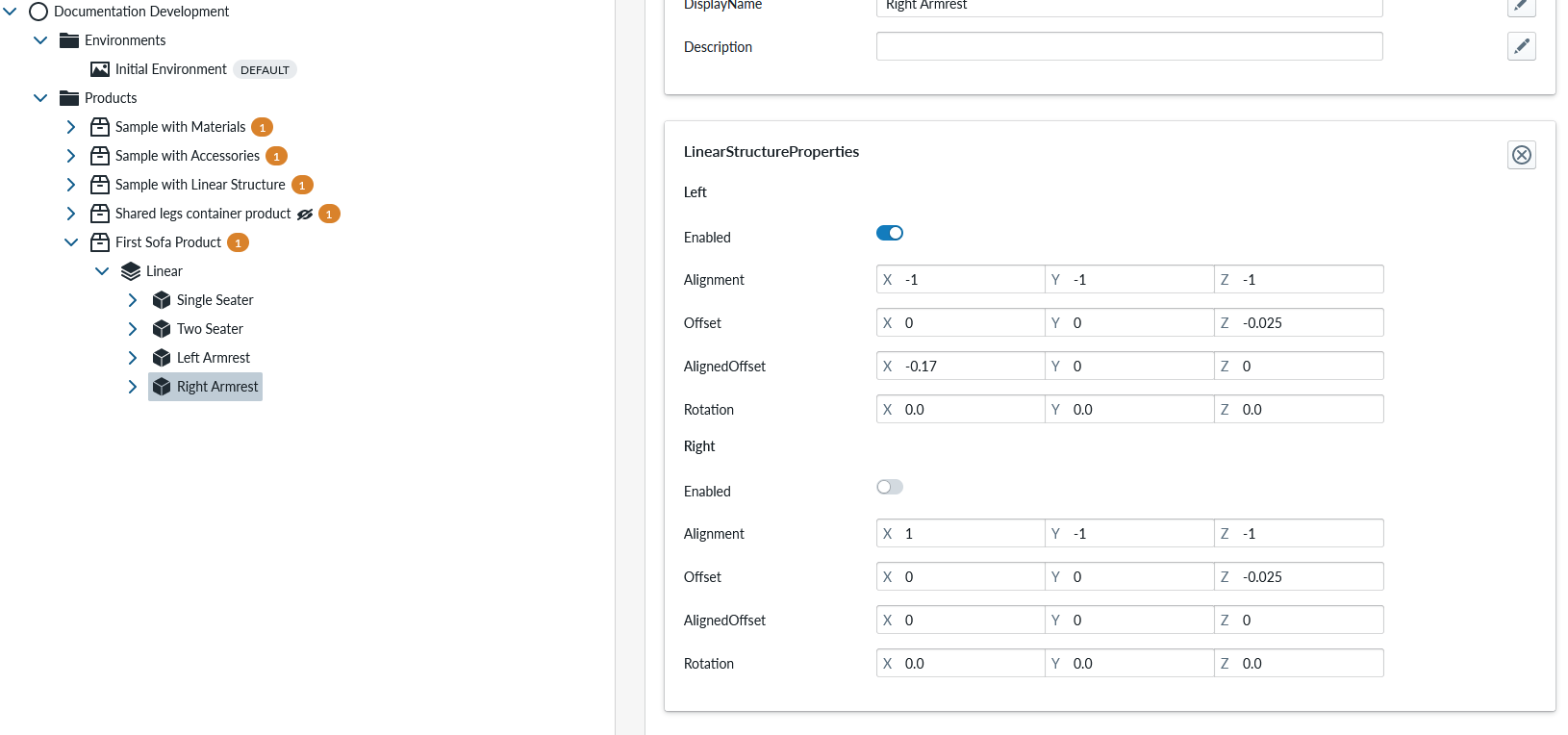
And the right armrest properties should be:
Regenerate the runtime products and open the planner.
When you add the single-seater and attach both armrests the sofa starts to look good.
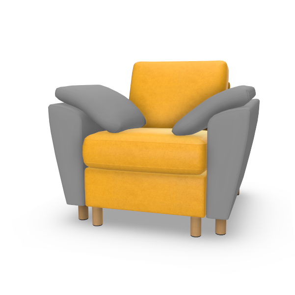
But you can still configure it wrong:
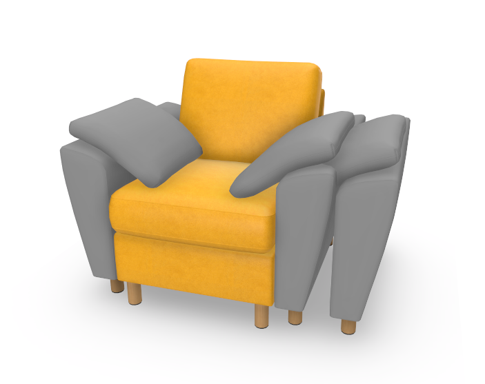
The rules of attachment allow elements to be added in the wrong place still. Lets fix this:
We do this by disabling attaching items to the left of the left armrest and disabling attaching to the right of right armrest. This can be done on the LinearStructureProperties of the LeftArmrest piece as below:
And to the Right Armrest as below:
Regenerate runtime products and open planner
Fix connectivity rules
We have almost fully working interconnectivity matrix, but with one problem: The armrests can be connected to eachother and nothing else in between. Lets correct this one still by going back to products and adding one final property set to the product.
In the configuration panel for the Linear Structure item, add ConnectivityMatrix Property set
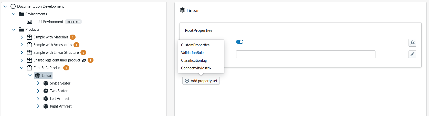
The matrix property set looks like this:
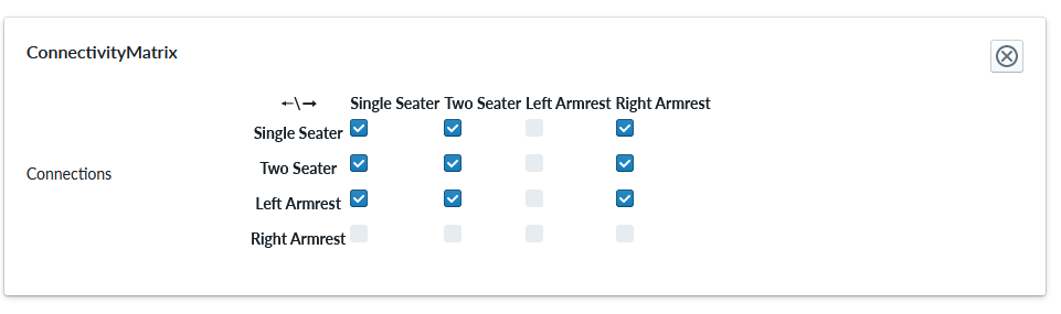
This matrix tells which item can be connected with which item on the left or right of the product. Eg. For the Right Armrest now (look at the columns (top) for right armrest, it says that any other piece than right armrest itself can be connected to the left of the right armrest. Right, except that Left Armrest should not be there. On the rows side (left) you can see that left armrest can be connected on the left with all pieces including right armrest of course.
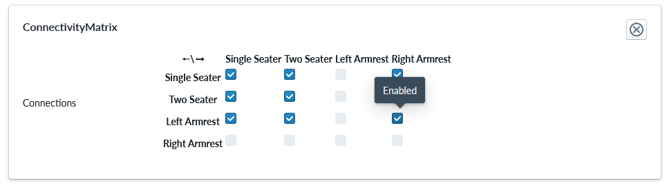
Lets remove the possibility to connect armrests with each other by disabling the marker between left armrest and right armrest:
The matrix should now look like:
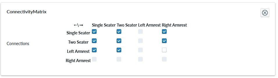
Regenerate the runtime products and open the planner. Now you no longer can add the armrests in wrong places and can only add the left armerest to the left end and right armrest to the right end.
add materials to armrests
Lets still copy and paste-as-reference the materials, regenerate the runtime products and check the composition. Hope you by now know how to do that, but go back to above to find where we copied and pasted-as-a-reference material between the Single Seater and Two Seater in the first place.
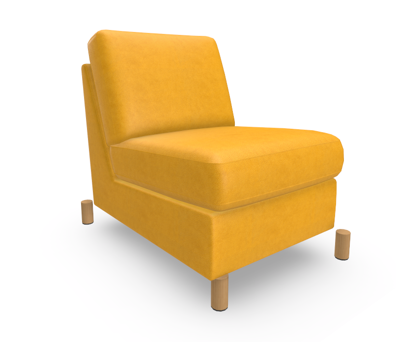
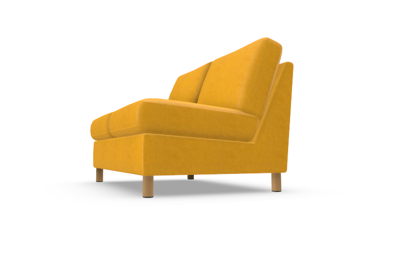
The sofa now looks like this:
further work to do
Theres still many things to refine:
- add in more modules (this you should be able to do based on this document on your own)
- add in corner modules (this requires that you rotate the position of the right side attachment corner using rotation parameter in LinearStructureProperties of an appropriate corner module item)
- alter the leg logic to avoid duplicate legs when modules are next to each other (done through scripting)
- making default composition for the planner (this you probably could figure our from the manager on your own if you tried)
All of these are somewhat outside of scope for “making your first sofa product” with VividWorks 3D ecommerce configurator.