Multi-connector Structure
Note
This is currently a preview feature and not available for all users.
Overview
Multi-connector structure is a structure logic that allows construction of modular products using parts and connectors. For any part in the composition, the configuration permits definition of connectors, which points to which another item can be connected. The role of parts inside the structure can be categorized based on the number of connectors they have. Parts with a single connector acts as end pieces, parts with two connectors can be used to build a linear segment, and parts with more than two connectors can be used to introduce branches to the structure. Additionally, at least one part must have a root connector, which is used to start the building by connecting it to the floor, wall, or a parent component.
Products using multi-connector structure can vary a lot in complexity. A simple configuration with a small number of parts and connectors works in a similar way than a Slot or a Linear Structure. On the other hand, complex three-dimensional patterns can be created by having many connectors with different rotation values.
Base properties
RootProperties

| Property Name | Type | Localized | Description |
|---|---|---|---|
| Enabled | Toggle/scripting | N | Toggle this to enable/disable all the elements under the multi-connector structure. If toggle is disabled, in the web app they will be hidden |
| DisplayName | Text Field | Y | Used as a subcategory name |
| ItemPlacement | Radio Button | N | When instantiating an element: - PlaceSingle (will show the possible placer one time only, then you need to click the element again.) - PlaceInSequence (will show the placer automatically after every addition, hence making adding new elements faster.) |
Optional property sets
Connectivity Matrix
Multi-connector Structure Connectivity Matrix Properties

| Property Name | Type | Localized | Description |
|---|---|---|---|
| Expand Matrix | Button | N | Opens a new panel for editing the connectivity matrix |
| Connections | chart view | N | Specifies if two connectors of connector types given by the row and column are allowed to form a connection |
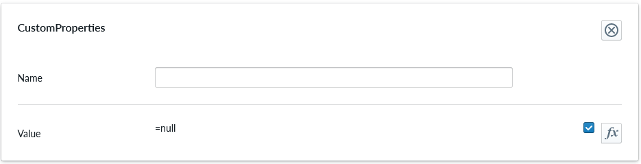
CustomProperties
Custom Property set (or sets) allow definition of logic that defines something that otherwise is not predefined in the system logic.
| Property Name | Type | Localized | Description |
|---|---|---|---|
| Name | Text field | N | The name of the custom property. It can be referred to from other scripts |
| Value | Scripting | N | Value or scripting logic that the property has |
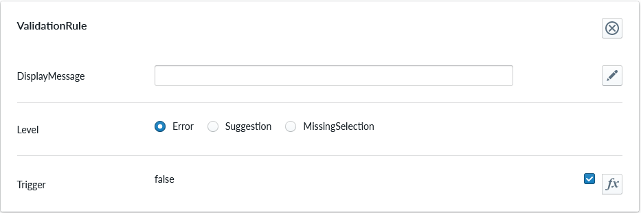
ValidationRule
Validation rule property set is used to define logic that can be useful to ensuring the item where the validation rule is will follow define rules.
| Property Name | Type | Localized | Description |
|---|---|---|---|
| DisplayMessage | Text Field | Y | Text that is shown on the Planner when the conditions of the rule are true |
| Level | Radio Button | N | Selection should the rule show error, suggestion or indicating something is missing |
| Trigger | Scripting | N | The logic that defines the validation rule |
Note
Validation rule level states correspond the next error levels. Error => "Error" Missing Selection => "Warning" Suggestion => "Info"
If the "add to cart" button is available, in case we have an error, the add to cart button will be disabled and not clickable until the error is fixed.
ClassificationTag
Classification tag allows the configurator to assign a custom tag name to a product item. These tags are exposed in the scripting system via the Tags property alongside automatic tags such as role:product and list:*. Use the built-in Contains function to check whether a component or structure has a given tag:
Contains(Tags, 'BottomMAT')
Contains(Root.Bottom.Component.Tags, 'BottomMAT')
| Property Name | Type | Localized | Description |
|---|---|---|---|
| Tag | Text field | N | A label that is associated with the item it's been configured to |
Per part configuration
The Parts that are placed as children of the Multi-connector Structure are considered as items where the logic of the Multi-connector Structure will apply. In order to the part to be available, at least one Connector property set must be added to it. By default, a newly added parts has three connectors: Left, Right and Ground. These are not mandatory and can be freely modified by the user.

| parameter | type | explanation |
|---|---|---|
| Name | text | Name of the connector. This name is used as a scripting property on the component, enabling this.<ConnectorName>.IsConnected expressions. Connector names must be unique on each part. |
| Type | text | Type of the connector |
| Alignment | 3D coordinate | the position of the connector in 3D space |
| Offset | 3D coordinate | absolute offset of the 3D mesh on the bounding box |
| AlignedOffset | 3D coordinate | relative offset of the 3D mesh on the bounding box |
| Rotation | degrees on 3d axises | degree of turn in the respective 3D axis relative to the bounding box |
| DisabledBeforeInstantiation | toggle | If enabled this connector is used only if the part is already placed in the scene. Setting this to true can be useful in symmetric corner parts in order to single out a primary connector. |
As opposed to linear structure, two connecting connectors must have an opposite rotation in order for them to connect in the right way. By default, the connector points up, and has an axial alignment in Z-axis. Refer to the 3D terminology and 3D configuration guides for detailed explanation of the parameters for alignment, offset, AlignedOffset and Rotation
Multi-connector Logic Connectivity Matrix
Connectivity matrix controls which connectors are allowed to join together. The matrix is formed on columns and rows and checkmarks crossing the column and row.
Scripting
Multi-connector structures and their components expose several built-in properties for use in scripts.
Structure-level properties
| Property | Type | Description |
|---|---|---|
| Components | Vector | Child components currently placed in the structure. |
| ComponentCount | Number | Total number of components currently placed in the structure. |
Component-level properties
Each component exposes connector properties in two complementary forms:
Named access — each connector is directly accessible by its authored Name. If a part has connectors named Left, Right, and Root, the component exposes top-level properties Left, Right, and Root, each being a connector record with the fields listed below. Named access is the recommended approach when connector names are known.
Important
Connector names must be unique on each part. A connector name that matches another scripting property on the same part (for example the indexed array accessor Connectors, a custom property, or another connector with the same name) causes a runtime data generation error.
Indexed access — the Connectors array provides zero-based indexed access in the authored order of the Connector property sets on the part. For example, if a part has three Connector property sets defined in the order Left, Right, Root, then Connectors[0] refers to Left, Connectors[1] to Right, and Connectors[2] to Root. Indexed access is useful when writing generic scripts that iterate over connectors by position.
| Property | Type | Description |
|---|---|---|
| <ConnectorName>.IsConnected | Boolean | True if the named connector is currently occupied by any connection. |
| <ConnectorName>.Offset | Vector3 | Absolute 3D offset of the named connector. |
| <ConnectorName>.AlignedOffset | Vector3 | Relative 3D offset (aligned) of the named connector. |
| Connectors[n].Offset | Vector3 | Absolute 3D offset of connector n. |
| Connectors[n].AlignedOffset | Vector3 | Relative 3D offset (aligned) of connector n. |
| Connectors[n].IsConnected | Boolean | True if connector n is currently occupied by any connection — including the component's own attachment connector, hosts for child components, and additional connections discovered via transform matching. |
| ConnectionCount | Number | Total number of connectors on this component that are currently occupied by any connection. |
Example expressions
Check whether the named Root connector is used to attach the component:
this.Root.IsConnected
Conditionally show something only when the Left connector is free:
NOT this.Left.IsConnected
Check whether the component uses its Root connector (index 2) to attach to the structure (indexed form):
this.Connectors[2].IsConnected
Get the total number of connected connectors on this component:
this.ConnectionCount
Show a part only when all its connectors are occupied:
this.ConnectionCount == 3
Check whether the current structure contains a child whose PartType custom property is Door:
Contains(PropertyValues(this.Components, "PartType"), "Door")
Note
A connector is considered connected if it participates in any connection: as the component's own join connector, as the parent-side connector for a child, or as either endpoint of an additional connection formed when multiple connectors align perfectly during placement. ConnectionCount counts all such connectors on the component.