General terminology and concepts
This page covers basic terminology in the 3D space relevant to the Vividworks 3D product configurator.
We aim not to be a comprehensive documentation about 3D space as a whole, but provide some key pointers to continue exploring and learning for people wanting to understand some technical terms or concepts further.
Khronos
The Khronos Group, Inc. is an open, non-profit, member-driven consortium of 170 organizations developing, publishing and maintaining royalty-free interoperability standards for 3D graphics, virtual reality, augmented reality, parallel computation, vision acceleration and machine learning. The Khronos Group specify the WebGL API and the glTF file format
Refer more:
Khronos Group website
Wikipedia article on Khronos group
GLTF & GLB
glTF (short form of Graphics Language Transmission Format or GL Transmission Format) is a standard file format for three-dimensional scenes and models. A glTF file uses one of two possible file extensions: .gltf (JSON/ASCII) or .glb (binary). Both .gltf and .glb files may reference external binary and texture resources.
VividWorks 3d product configurator utilizes glTF 2.0 Separate file format where the data is split into multiple files. .gltf (json/ASCII) file containing metadata in JSON format and .bin file containing the polygon mesh data. Additionally the 3d model related materials may be incorporated and referenced by the model in the .gltf file. The glTF files are uploaded in a .zip package into the configurator.
.glb aims to bundle all the related files binary files like textures into one file (binary). Benefit of glb is that files are easier to manage on disk file system (think of string the files to be uploaded for use). But they may bring up the total size (due to base-64 encoding) and not support progressive or on-demand loading, so if optimizing for size and performance, prefer using gLTF.
Refer more:
Khronos Groups gltf specification
Wikipedia article on gltf
Mesh or Polygon Mesh
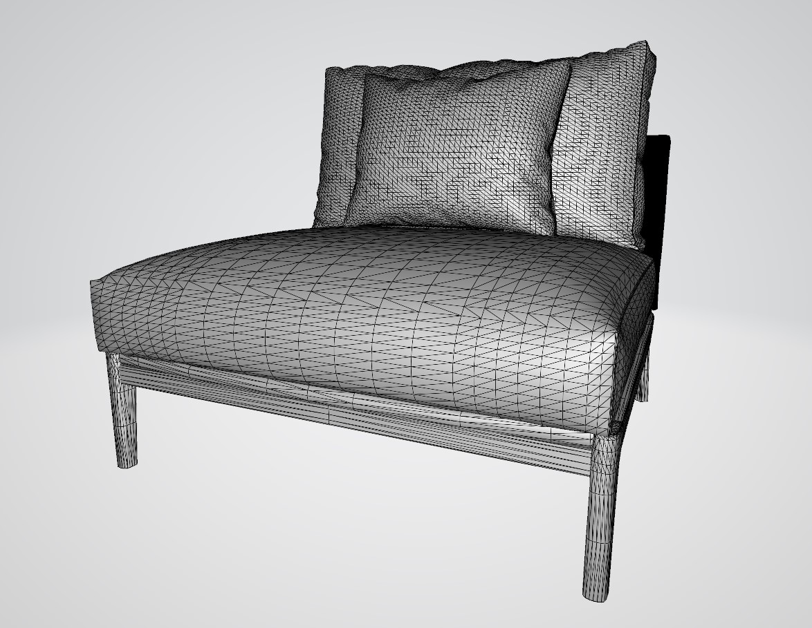
3D objects are a collection of vertices (points in 3D space), edges (lines between vertices) and faces (triangles or quadrilaterals between 3 or 4 vertices connected with edges) that represent the surface form of the 3D object. The more vertices and faces the 3D object has, the more fine-grained is the detail of it, but rendering such 3D objects becomes slower due to the increased amount of mathematical calculations needed. The optimization of 3D meshes by adding more detail through creation of vertices or removal of detail by merging vertices or by editing the model by editing the vertices is crucial for achieving photo-realism. Together with Textures, 3D meshes form the basis of 3D rendering.
Here is an example 3D mesh of a sofa element:
Refer more:
Wikipedia article on Polygon Meshes
Materials or Textures
Texture mapping is a method for defining high frequency detail, surface texture, or color information on a computer-generated graphic or 3D model mesh. Within this document, a Texture or Material refers to files that contain Texture maps that the software uses to produce realistic representation of the surface of the product. With Textures, many aspects of photo-realism can be achieved. For example, color, unevenness of surface, bumps, reflection, opacity, transparency are aspects that Texture maps permit achieving.
Refer more:
Wikipedia article on Textures
OpenGL
WebGL is a derived standard from OpenGL (short for Open Graphics Library). It is maintained by Khronos Group, like WebGL and defines an api for rendering 2D and 3D vectors by hardware, nowadays GPU (Graphics Processing Units) achieving Hardware-accelerated rendering.
Refer more:
Official website for OpenGL
Wikipedia article on OpenGL
WebGL
WebGL (Short for Web Graphics Library) is a JavaScript API for rendering interactive 2D and 3D graphics within any compatible web browser without the use of plug-ins. WebGL is fully integrated with other web standards, allowing GPU-accelerated usage of physics and image processing and effects as part of the web page canvas. WebGL elements can be mixed with other HTML elements and composited with other parts of the page or page background.
VividWorks 3D product configurator uses WebGL technology for the 3D rendering. The device that you or your customer uses must be compatible with WebGL. WebGL report (link below) can be used to determine the compatibility. Modern mobile phones, tablets and computers all support WebGL, but SmartTVs and other browser enabled devices may have limited support.
Refer more:
Khronos group WebGL page
Wikipedia article on webgl
Tool for checking devices webGL compatibility
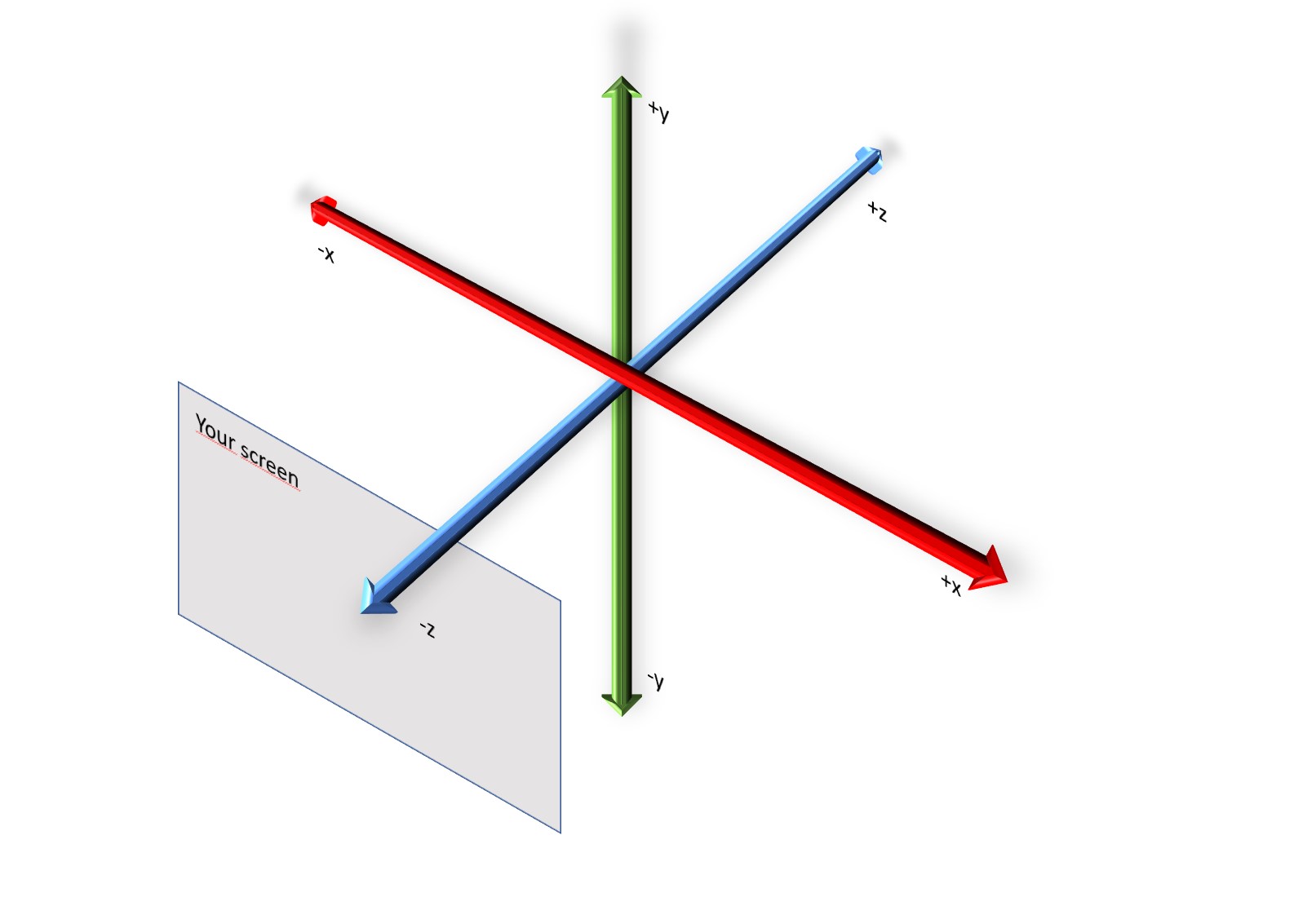
Coordinate system
The coordinate system is essential in the context of 3D. For 3D, it is important to define the direction of 3 coordinate axes: x, y, z. In physical world, when looking at an object we think width, height and depth. Understanding how x, y, z map onto the concept of width, height and depth is the foundation of the coordinate system. The 3D product configurator uses the 'right-hand rule'. Have your hand so that the right-hand thumb is pointed up and the rest of the fingers are curved naturally. Keeping your hand like this, when you point the thumb towards the positive direction of the axis you consider rotation, your other fingers will point towards the positive rotation direction.
Rotation in the coordinate system
The aspect of rotation is usually an important matter to understand in the 3D space. For example, it is important to know when the rotation direction is positive or negative. It is also important to understand that in 3D, rotation can happen in all the axes.
In the 3D product configurator, the rotation is based on the right-hand rule. Have your right hand so that the thumb is pointed up and the rest of the fingers are curved naturally. Keeping your hand like this, when you point the thumb towards the positive direction of the axis you are considering for the rotation, your other fingers will point towards the positive rotation direction.
An alternative way is viewing the axis along where rotation is happening, towards the positive infinity. The positive rotation direction happens clock-wise and the negative rotation direction happens counter-clockwise.
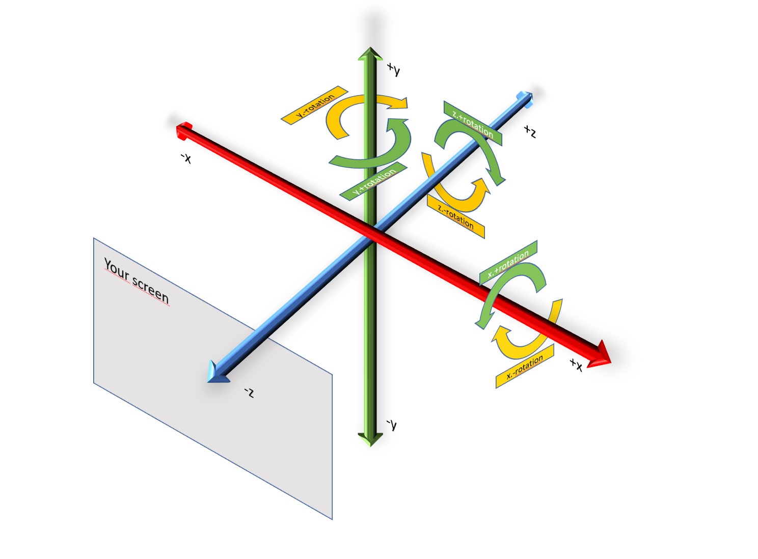
In the picture above, the green arrow shows positive rotation along an axis and yellow arrow shows negative rotation direction.
Understanding rotation and the related axis where the rotation happens, is vital to place attachment points, accessories and other items. There are many ways the rotation of the connecting point or other settings are helpful in making configuration of products possible in 3D. In our tutorial of the Sofa, two elements (the "corner module" and the "30 degree corner module") have their left and right attachment points rotated in order to attach the next piece correctly.
Refer more:
Wikipedia article on right-hand rule
Vector or 3D coordinate
3D uses a system to position items, typically points in 3D coordinates from the origin (coordinates [x: 0, y:0, z:0]) as vectors. These vectors can represent also direction and length from the origin and be mathematically manipulated further through the creation of other vectors. The distance from the origin can always be represented by the distance from the 3 individual axes x, y, and z. Additionally, one can use the coordinates to manipulate in relative terms, so x: +1 from previous position of x:. The 3D product configurator uses mostly relative coordinates, but it can use absolute ones too.
 Aboalbiss, CC BY-SA 3.0 http://creativecommons.org/licenses/by-sa/3.0/, via Wikimedia Commons
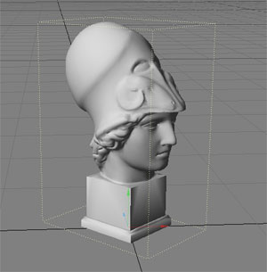
Bounding Box
In 3D, bounding box refers to the dimensions of the 3D object in it's maximum boundaries.
CC BY 2.0, https://commons.wikimedia.org/w/index.php?curid=641403
This is useful in many ways, for example to detect if the objects are colliding or nearby each other, or to identify the dimensions and measurements of the object.
Collision detection
As the 3D space has no physical characteristics, we need to mathematically calculate how objects touch or collide with each other. The collision detection is algorithmically done either at mesh vertex level or at bounding box level. This mathematical capability allows the 3D product configurator to allow placing objects that do not overlap with each other in the 3D scene, which is useful and important visually and for the accuracy of the product composition measurements.
Currently, collision detection is automatic when using the Free Placement structure logic for child parts, under the logic to manage the placement of the objects in the 3D space.
Snapping
When objects are near to each other, Snapping attaches them together in the snap point or snap side. This helps to avoid the user from leaving tiny gaps or place parts just a teeny bit unaligned in the scene.
Currently, Snapping is automatic in the Free Placement structure logic when the size parameters are defined for all the parts in their root parameters.
UV Mapping
UV mapping is the 3D modeling process of projecting a 2D image to a 3D model's surface for texture mapping. The letters "U" and "V" denote the axes of the 2D texture because "X", "Y", and "Z" are already used to indicate the axes of the object in the 3D space.
Wikipedia Article on UV Mapping
3D modelling terminology
Vertex
Vertex (plural: vertices) are points in 3D space that connect with each other through edges to form polygons.
Edge
Two vertices connected together form an edge. Three or more edges connected together form a face
Face
Face is a plane defined by three or more edges connected together. The faces usually consist of triangles, quadrilaterals, or other types of polygons (n-gons). Groups of faces connected to each other form a 3D Mesh.
Texel
Texel is short for Texture Pixel. While it behaves like any other pixel, the reason of a texture pixel being referred like this, is related to the Textures (materials in 3D product configurator) being overlaid on top of 3D meshes to render the surface in a realistic manner.
This evaluation is important when one zooms in or out the 3D mesh, so that the texture pixel in rendering would be smaller or larger than the rendered pixel. There are parameters in the Material and Material Property sets (especially the TilingTexture property set) that affect how the system evaluates these conditions. This has a direct impact on the visual quality.