Linear Structure
Overview
Linear structure is a structure logic that allows construction of modular products using 'left-right' logic. This means that for any item in the composition, the configuration permits definition of connectors (points to which another item can be connected) both on the 'left' and/or 'right' of the item. While left and right have connotation in certain way, the left and right connectors may be applied more freely in practice, for example to develop corner or angled elements.
For configuring assembly rules with this logic, there's two fundamental sets of configuration. The configuration specific to each part (see: per part configuration) and the Linear Structure logic configuration (see: Linear Logic Connectivity Matrix). The connectivity matrix builds on the per part configuration, hence you should study the configuration documentation in that order.
You add Linear Structure Logic to the product tree by adding the logic to the product in question.
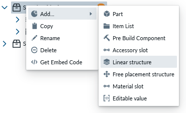
You then either add new parts (see: add items in product tree or move parts as children under the Linear logic (see: moving items in product tree)
Base properties
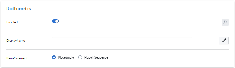
RootProperties
| Property Name | Type | Localized | Description |
|---|---|---|---|
| Enabled | Toggle/scripting | N | Toggle this to enable/disable all the elements under the linear structure. If toggle is disabled, in the web app they will be hidden |
| DisplayName | Text Field | Y | Used as a subcategory name |
| ItemPlacement | Radio Button | N | When instantiating an elemen: - PlaceSingle (will show the possible placer one time only, then you need to click the element again.) - PlaceInSequence (will show the placer automatically after every addition, hence making adding new elements faster.) |
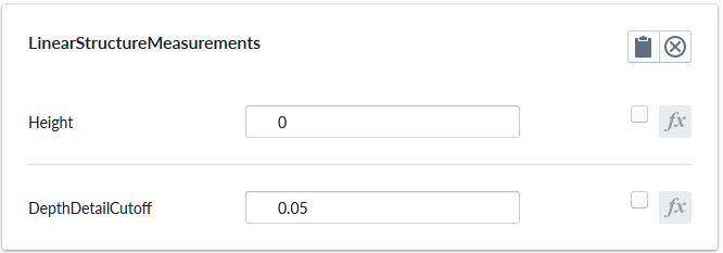
LinearStructureMeasurements
Linear structure measurements properties
| Property Name | Type | Localized | Description |
|---|---|---|---|
| Height | Number | N | The height offset for measure stick positions |
| DepthDetailCutoff | Number | N | The minimum lenght of depthwise measures before they are aggregated together |
Optional property sets
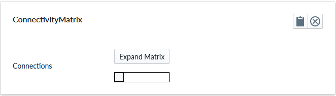
Connectivity Matrix
Connectivity matrix properties
| Property Name | Type | Localized | Description |
|---|---|---|---|
| Expand Matrix | Button | N | Opens a new panel for editing the connectivity matrix |
| Connections | chart view | N | the mapping 'left' to 'right' of all parts defined under this Linear Structure see Linear Logic Connectivity Matrix |
MaxComponentLimit
Maximum component limit properties
Use this property set on the Linear Structure itself when you want to limit the total number of components that can be added to the structure.
| Property Name | Type | Localized | Description |
|---|---|---|---|
| Count | Number / scripting | N | Maximum allowed number of components in the linear structure. Script values are floored to an integer. Use -1 for unlimited. |
| ValidationMessage | Text Field | Y | Localized validation message shown when the current composition exceeds the configured total count, for example after a scripted value decreases. |
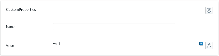
CustomProperties
Custom Property set (or sets) allow definition of logic that defines something that otherwise is not predefined in the system logic.
| Property Name | Type | Localized | Description |
|---|---|---|---|
| Name | Text field | N | The name of the custom property. It can be referred to from other scripts |
| Value | Scripting | N | Value or scripting logic that the property has |
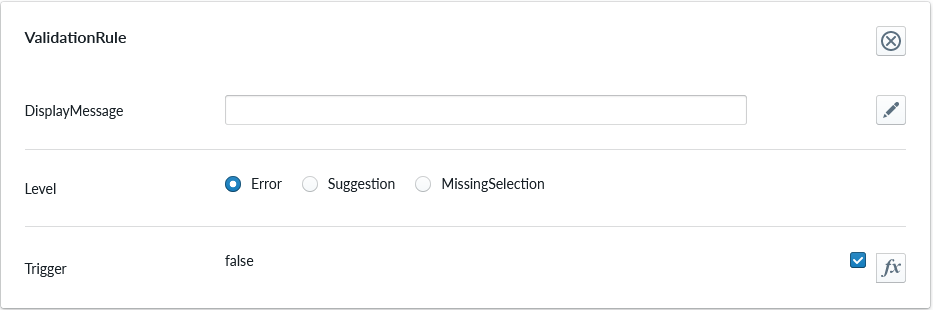
ValidationRule
Validation rule property set is used to define logic that can be useful to ensuring the item where the validation rule is will follow define rules.
| Property Name | Type | Localized | Description |
|---|---|---|---|
| DisplayMessage | Text Field | Y | Text that is shown on the Planner when the conditions of the rule are true |
| Level | Radio Button | N | Selection should the rule show error, suggestion or indicating something is missing |
| Trigger | Scripting | N | The logic that defines the validation rule |
Note
Validation rule level states correspond the next error levels. Error => "Error" Missing Selection => "Warning" Suggestion => "Info"
If the "add to cart" button is available, in case we have an error, the add to cart button will be disabled and not clickable until the error is fixed.
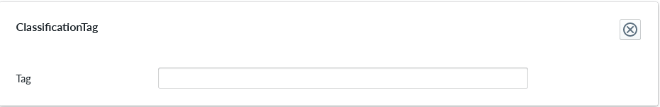
ClassificationTag
Classification tag allows the configurator to assign a custom tag name to a product item. These tags are exposed in the scripting system via the Tags property alongside automatic tags such as role:product and list:*. Use the built-in Contains function to check whether a component or structure has a given tag:
Contains(Tags, 'BottomMAT')
Contains(Root.Bottom.Component.Tags, 'BottomMAT')
| Property Name | Type | Localized | Description |
|---|---|---|---|
| Tag | Text field | N | A label that is associated with the item it's been configured to |
Scripting
Linear structures expose built-in properties that can be used in structure-level scripts.
| Property | Type | Description |
|---|---|---|
| Components | Vector | Child components currently placed in the structure. |
| ComponentCount | Number | Number of components currently placed in the structure. |
| FirstComponent | Part or null | First component in the structure, or null when the structure is empty. |
| LastComponent | Part or null | Last component in the structure, or null when the structure is empty. |
Example: check whether the current linear structure contains a child whose PartType custom property is Door.
Contains(PropertyValues(this.Components, "PartType"), "Door")
Per part configuration
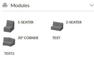
The Parts that are placed as childs of the Linear Structure are considered as items where the logic of the Linear Structure will apply. In the image below, the parts from '1-seater' to 'Test2' are child items of the Linear Structure logic named 'Linear'.
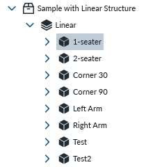
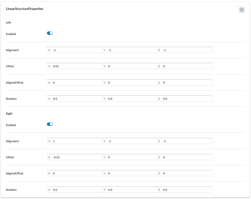
All child items of Linear Structure logic will introduce a property set called "LinearStructureProperties" and the property set will define parameters for the connection points on the 'left' and 'right'.
| parameter | type | explanation |
|---|---|---|
| left or right | toggle | the connection point on this side is enabled or not |
| Alignment | 3D coordinate | the position of the connector in 3D space |
| Offset | 3D coordinate | absolute offset of the 3D mesh on the bounding box |
| AlignedOffset | 3D coordinate | relative offset of the 3D mesh on the bounding box |
| Rotation | degrees on 3d axises | degree of turn in the respective 3D axis relative to the bounding box |
| MaxComponentsLeft | number | maximum number of components allowed strictly on the left side of this part. Use -1 for unlimited. |
| MaxComponentsRight | number | maximum number of components allowed strictly on the right side of this part. Use -1 for unlimited. |
If both structure-level and part-level maximum component limits are configured, the strictest applicable limit is used. Side-specific limits also participate in add and replace availability for linear structure edits.
Refer to the 3D terminology and 3D configuration guides for detailed explanation of the parameters for alignment, offset, AlignedOffset and Rotation
With the 4 parameters, one can build many kinds of sellable items like modular sofas and other furniture, industrial production lines based on module-subsystems. The rotation parameter is used to rotate the connection point by some degrees, with which you can achieve corner pieces, angled pieces and other modules that dont exactly align with other items in absolutely linear form.
Alignment
The alignment parameter defines the location of the connector in 3D space relative to the parts' 3D model. The 3D product configurator is scaled to 1 cm equaling 0.01 distance in 3D space, thus setting the alignment parameter is rather straight forward when you know the physical dimensions of the part in question and potentially experiment the positioning when defining compositions.
When editing the values, negative values on x: moves the connection point left relative to the front of the part and positive to the right. Likewise negative y: moves point down and positive up. Negative z: moves the connector closer to the front and positive moves it further away
Offset
AlignedOffset
Rotation
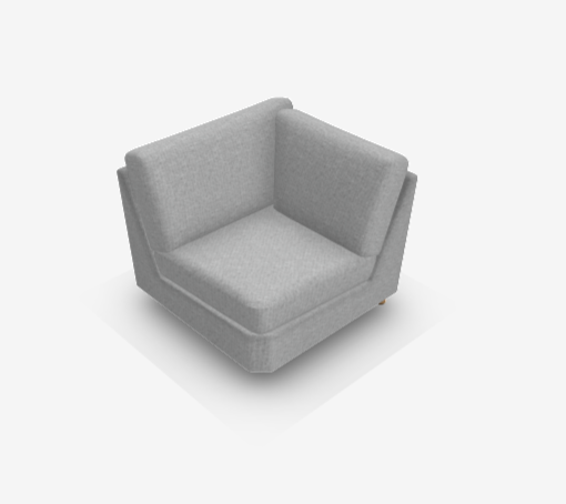
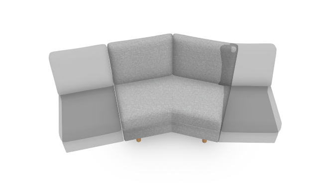
When working with the connector rotation parameter, what you are aiming to do is to rotate the plane on the proper axis toward the right direction. On the sofa example, the 30-degree module is used:
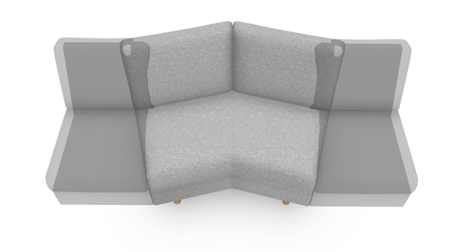
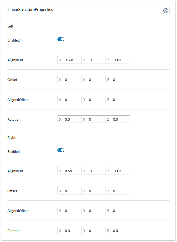
In the above pictures, the rotation parameters are both 0 and thus the 3D view shows connection points straight on the bounding box.
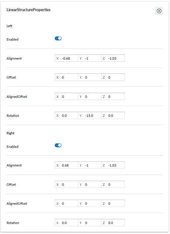
When the rotation parameter of the left connector y: axis is changed by -15.0 degrees ie rotated counter-clockwise by 15 degree, the connector aligns properly with the 3d model connection on the next item.
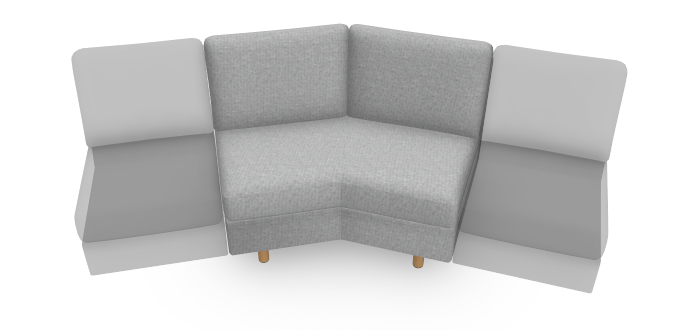
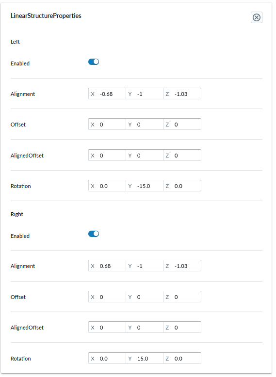
And when the rotation parameter of the right connector y: axis is change by 15.0 degrees ie. rotated clockwise by 15 degrees, the connector aligns properly with the 3d model connection on the next item.
Refer to the 3D model configuration guide for rotation guidance.
You can achieve connection point alignment of many structure elements using the rotation parameter alone, but occasionally you additionally need to adjust alignment which affects the placement of the connection point.
Linear Logic Connectivity Matrix
When items have their individual connectors defined, it becomes easier to define the connectivity matrix. The matrix is formed on columns and rows and checkmarks crossing the column and row. The rows represent item on the left and the column represent item on the right and the checkmark means "this item on the left can be connected with this item on the right". This is very flexible and powerful way to define items that can only be attached to a certain other item on certain side, like arm rests or other elements that end the composition (ie. have connector only on one side), but also certain modules only attaching to a certain other module and not all modules. The planner application will leverage the connectivity information and help the user to select appropriate placement and when there only can be one, automatically place the item there.
Below you can find an example picture of a connectivity matrix:
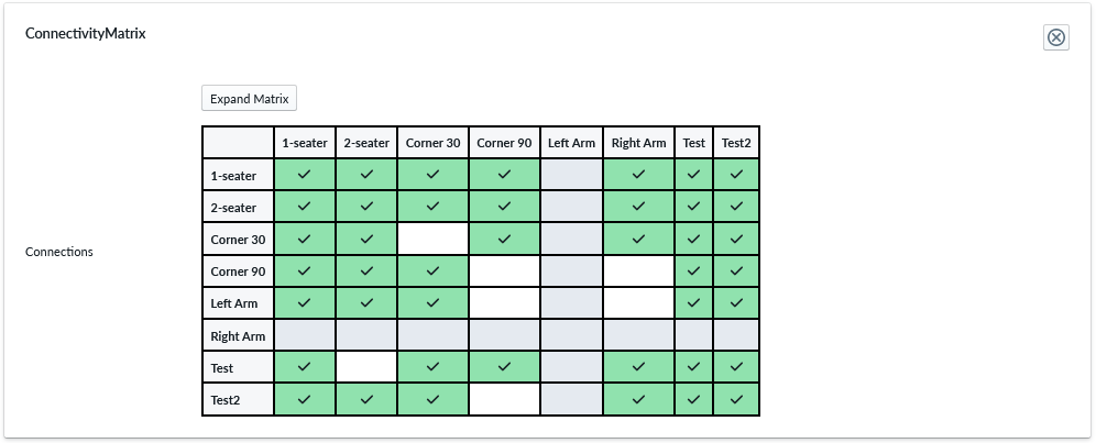
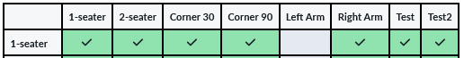
If you read it from the 1st row 1-Seater to the right, you can see that 1-seater can be connected with all other items than a LeftArmRest on its right connector. In the planner, this works out so, that you can only see the modules you could attach and the side in which they can be attached.
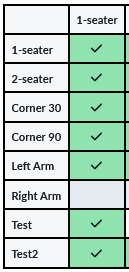
If you read the 1st column 1-seater to the left, you can see that 1-seater can be connected with all other items than RightArmRest on it's left connector.
If you read the connectivity matrix for 90-degree corner piece, you'll notice that it cannot be connected with itself, nor with either of the arm rests. This gets automatically reflected on the modules menu when the piece is placed, so the only available modules are the valid ones when 90-corner is selected. This rule system ensures that only permitted combinations can be placed by the user.